<< Chapter < Page Chapter >> Page >
  • Describe the electric and magnetic waves as they move out from a source, such as an AC generator.

We can get a good understanding of electromagnetic waves    (EM) by considering how they are produced. Whenever a current varies, associated electric and magnetic fields vary, moving out from the source like waves. Perhaps the easiest situation to visualize is a varying current in a long straight wire, produced by an AC generator at its center, as illustrated in [link] .

A long straight gray wire with an A C generator at its center, functioning as a broadcast antenna for electromagnetic waves, is shown. The wave distributions at four different times are shown in four different parts. Part a of the diagram shows a long straight gray wire with an A C generator at its center. The time is marked t equals zero. The bottom part of the antenna is positive and the upper end of the antenna is negative. An electric field E acting upward is shown by an upward arrow. Part b of the diagram shows a long straight gray wire with an A C generator at its center. The time is marked t equals capital T divided by four. The antenna has no polarity marked and a wave is shown to emerge from the A C source. An electric field E acting upward as shown by an upward arrow. The electric field E propagates away from the antenna at the speed of light, forming part of the electromagnetic wave from the A C source. A quarter portion of the wave is shown above the horizontal axis. Part c of the diagram shows a long straight gray wire with an A C generator at its center. The time is marked t equals capital T divided by two. The bottom part of the antenna is negative and the upper end of the antenna is positive and a wave is shown to emerge from the A C source. The electric field E propagates away from the antenna at the speed of light, forming part of the electromagnetic wave from the A C source. A quarter portion of the wave is shown below the horizontal axis and a quarter portion of the wave is above the horizontal axis. Part d of the diagram shows a long straight gray wire with an AC generator at its center. The time is marked t equals capital T. The bottom part of the antenna is positive and the upper end of the antenna is negative. A wave is shown to emerge from the A C source. The electric field E propagates away from the antenna at the speed of light, forming part of the electromagnetic wave from the A C source. A quarter portion of the wave is shown above the horizontal axis followed by a half wave below the horizontal axis and then again a quarter of a wave above the horizontal axis.
This long straight gray wire with an AC generator at its center becomes a broadcast antenna for electromagnetic waves. Shown here are the charge distributions at four different times. The electric field ( E size 12{E} {} ) propagates away from the antenna at the speed of light, forming part of an electromagnetic wave.

The electric field    ( E size 12{E} {} ) shown surrounding the wire is produced by the charge distribution on the wire. Both the E size 12{E} {} and the charge distribution vary as the current changes. The changing field propagates outward at the speed of light.

There is an associated magnetic field    ( B size 12{B} {} ) which propagates outward as well (see [link] ). The electric and magnetic fields are closely related and propagate as an electromagnetic wave. This is what happens in broadcast antennae such as those in radio and TV stations.

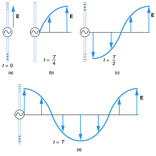
Closer examination of the one complete cycle shown in [link] reveals the periodic nature of the generator-driven charges oscillating up and down in the antenna and the electric field produced. At time t = 0 size 12{t=0} {} , there is the maximum separation of charge, with negative charges at the top and positive charges at the bottom, producing the maximum magnitude of the electric field (or E size 12{E} {} -field) in the upward direction. One-fourth of a cycle later, there is no charge separation and the field next to the antenna is zero, while the maximum E size 12{E} {} -field has moved away at speed c size 12{c} {} .

As the process continues, the charge separation reverses and the field reaches its maximum downward value, returns to zero, and rises to its maximum upward value at the end of one complete cycle. The outgoing wave has an amplitude    proportional to the maximum separation of charge. Its wavelength     λ size 12{ left (λ right )} {} is proportional to the period of the oscillation and, hence, is smaller for short periods or high frequencies. (As usual, wavelength and frequency     f size 12{ left (f right )} {} are inversely proportional.)

Electric and magnetic waves: moving together

Following Ampere’s law, current in the antenna produces a magnetic field, as shown in [link] . The relationship between E size 12{E} {} and B size 12{B} {} is shown at one instant in [link] (a). As the current varies, the magnetic field varies in magnitude and direction.

Part a of the diagram shows a long straight gray wire with an A C generator at its center, functioning as a broadcast antenna. The antenna has a current I flowing vertically upward. The bottom end of the antenna is negative and the upper end of the antenna is positive. An electric field is shown to act vertically downward. The magnetic field lines B produced in the antenna are circular in direction around the wire. Part b of the diagram shows a long straight gray wire with an A C generator at its center, functioning as a broadcast antenna. The electric field E and magnetic field B near the wire are shown perpendicular to each other. Part c of the diagram shows a long straight gray wire with an A C generator at its center, functioning as a broadcast antenna. The current is shown to flow in the antenna. The magnetic field varies with the current and propagates away from the antenna as a sine wave in the horizontal plane. The vibrations in the wave are marked as small arrows along the wave.
(a) The current in the antenna produces the circular magnetic field lines. The current ( I size 12{I} {} ) produces the separation of charge along the wire, which in turn creates the electric field as shown. (b) The electric and magnetic fields ( E size 12{E} {} and B size 12{B} {} ) near the wire are perpendicular; they are shown here for one point in space. (c) The magnetic field varies with current and propagates away from the antenna at the speed of light.

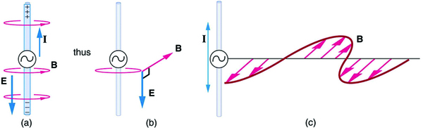
The magnetic field lines also propagate away from the antenna at the speed of light, forming the other part of the electromagnetic wave, as seen in [link] (b). The magnetic part of the wave has the same period and wavelength as the electric part, since they are both produced by the same movement and separation of charges in the antenna.

The electric and magnetic waves are shown together at one instant in time in [link] . The electric and magnetic fields produced by a long straight wire antenna are exactly in phase. Note that they are perpendicular to one another and to the direction of propagation, making this a transverse wave    .

A part of the electromagnetic wave sent out from the antenna at one instant in time is shown. The wave is shown with the variation of two components, E and B, moving with velocity c. E is a sine wave in one plane with small arrows showing the vibrations of particles in the plane. B is a sine wave in a plane perpendicular to the E wave. The B wave has arrows to show the vibrations of particles in the plane. The waves are shown intersecting each other at the junction of the planes because E and B are perpendicular to each other. E and B are in phase, and they are perpendicular to one another and to the direction of propagation.
A part of the electromagnetic wave sent out from the antenna at one instant in time. The electric and magnetic fields ( E size 12{E} {} and B size 12{B} {} ) are in phase, and they are perpendicular to one another and the direction of propagation. For clarity, the waves are shown only along one direction, but they propagate out in other directions too.

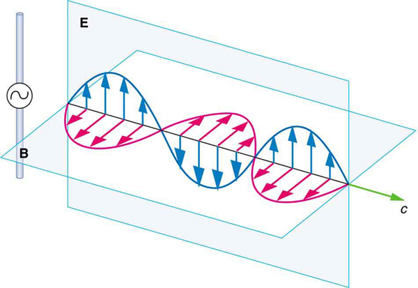
Electromagnetic waves generally propagate out from a source in all directions, sometimes forming a complex radiation pattern. A linear antenna like this one will not radiate parallel to its length, for example. The wave is shown in one direction from the antenna in [link] to illustrate its basic characteristics.

Instead of the AC generator, the antenna can also be driven by an AC circuit. In fact, charges radiate whenever they are accelerated. But while a current in a circuit needs a complete path, an antenna has a varying charge distribution forming a standing wave    , driven by the AC. The dimensions of the antenna are critical for determining the frequency of the radiated electromagnetic waves. This is a resonant    phenomenon and when we tune radios or TV, we vary electrical properties to achieve appropriate resonant conditions in the antenna.

Receiving electromagnetic waves

Electromagnetic waves carry energy away from their source, similar to a sound wave carrying energy away from a standing wave on a guitar string. An antenna for receiving EM signals works in reverse. And like antennas that produce EM waves, receiver antennas are specially designed to resonate at particular frequencies.

An incoming electromagnetic wave accelerates electrons in the antenna, setting up a standing wave. If the radio or TV is switched on, electrical components pick up and amplify the signal formed by the accelerating electrons. The signal is then converted to audio and/or video format. Sometimes big receiver dishes are used to focus the signal onto an antenna.

In fact, charges radiate whenever they are accelerated. When designing circuits, we often assume that energy does not quickly escape AC circuits, and mostly this is true. A broadcast antenna is specially designed to enhance the rate of electromagnetic radiation, and shielding is necessary to keep the radiation close to zero. Some familiar phenomena are based on the production of electromagnetic waves by varying currents. Your microwave oven, for example, sends electromagnetic waves, called microwaves, from a concealed antenna that has an oscillating current imposed on it.

Section summary

  • Electromagnetic waves are created by oscillating charges (which radiate whenever accelerated) and have the same frequency as the oscillation.
  • Since the electric and magnetic fields in most electromagnetic waves are perpendicular to the direction in which the wave moves, it is ordinarily a transverse wave.

Get Jobilize Job Search Mobile App in your pocket Now!

Get it on Google Play Download on the App Store Now


Source:  OpenStax, Concepts of physics. OpenStax CNX. Aug 25, 2015 Download for free at https://legacy.cnx.org/content/col11738/1.5
Google Play and the Google Play logo are trademarks of Google Inc.

Notification Switch

Would you like to follow the 'Concepts of physics' conversation and receive update notifications?

Ask