

| << Chapter < Page | Chapter >> Page > |
SSPD_Chapter 7_Part 4_CMOS design rules_continued3
7.4.3.1. Device Well-Device Well spacing should be 3Lambda.

7.4.4. Metal Overlay on Diffusion Contact/Poly Si Contact/Metal 1,Metal 2 Via.
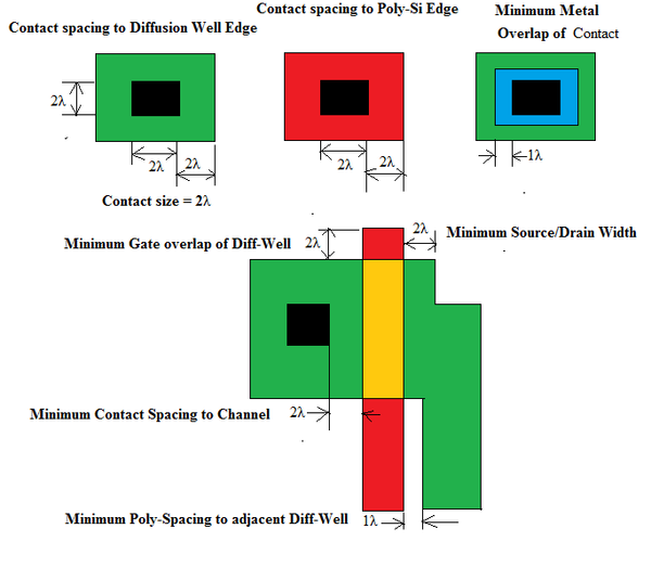
In Figure 7.4.4.1 we give the design rules for Contact Size and Contact Spacing with respect to Diffusion Well/PolySi Edge /Channel, minimum poly-spacing with respect to adjacent diffusion well, minimum gate overlap of Diffusion –Well and minimum Source/Drain width according to CUMF NMOS Design Rules. Contact area is marked black.
In Figure 7.4.4.2 we give the definition of Via and how through Vias different level of metallization are interconnected. Minimum distance between two vias is 3Lambda.

7.4.5. Rules for CMOS Layout.
CMOS can be fabricated by the following three methods:
We will choose N-Well in P-Substrate. In this case we have the following three requirements:
1. Definition of n-well area
2. Threshold implant of two types of transistor
3. Definition of source and drains regions for the NMOS and PMOS.
To ensure the separation of the PMOS and NMOS devices, n-well supporting PMOS is 6lambda away from the active area of NMOS transistor.
This is to prevent overlap of the associated regions as shown in Figure 7.4.5.1.
Simplest MOS processes require only 4 masks. It can be p-channel or n-channel FETs, not both.
In CMOS we have n and p transistors transistors simultaneously and therefore CMOS is a major improvement over NMOS or PMOS technology.

7.4.5.1. Complete CMOS Layout.
We have seen that for maximum noise margin, CMOS should have symmetrical operation around Vin = Vout = 0.5 V DD . This requires that special transconductance parameter β N = β P . Since mobility of majority carriers in PMOS is half that of majority carriers in NMOS hence (W/L) P = 2× (W/L) N . Based on this inference the CMOS layout is given in Figure 7.4.5.2.

Notification Switch
Would you like to follow the 'Solid state physics and devices-the harbinger of third wave of civilization' conversation and receive update notifications?

|
|

|
|

|
|

|
|

|
|

|
|

|
|

|
|

|
|

|