

| << Chapter < Page | Chapter >> Page > |
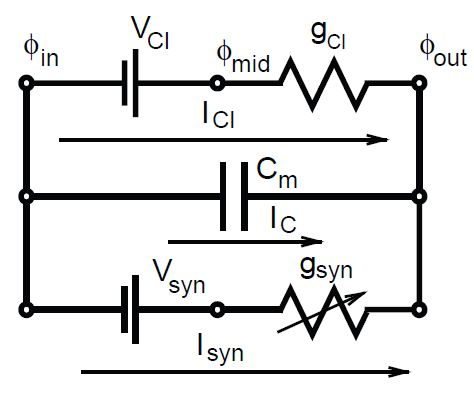
We model the place cell's voltage using the Conductance-based Integrate and Fire model, as pictured by the circuit diagram above. Cell voltage, or the voltage difference across the cell membrane, which we define as , is modified via the flow of charged ions across the cell membrane. In our integrate and fire model, we implement three parallel components through which cell voltage is adjusted. The first parallel component represents our leak current resulting from the flow of chloride ions through leaky channels. The chloride ions will travel across the membrane to reach their resting potential, which we denote as or (used later in the text), of -70 mV. The flow of ions is limited by a conductance , which remains fixed at a value of 1 mS/cm . S represents Siemens, the reciprocal of the unit of resistance . When we put these terms together using Ohm's law and solve for chloride current, we get:
The second parallel component of the integrate and fire model consists of a capacitor, indicative of the cell membrane's ability to separate electrical charge (in the form of ions). For this component, the capacitive current, represents the current due to the change in transmembrane voltage. This current takes the following form:
Here, denotes the membrane's capacitance, or ability to store charge. We use the value of = 20 F/cm .
The third parallel component of our circuit involves current from synaptic inputs. This input will act as the driving force for depolarization (in this setup we do not use any inhibitory synapses). As such, we use a excitatory reversal potential of = 0 mV, which will help raise the cell voltage toward the firing threshold in the presence of input. The magnitude of the input current is limited by synaptic conductance, which we denote in the circuit diagram (also referred to as ). The synaptic conductance, unlike the leak conductance of the chloride channels, is a variable conductance (denoted by the arrow through the resistor) whose magnitude is discussed in the next section. The synaptic input current is represented by the following:
Since these three currents are in parallel, we can use Kirchhoff's current law, which states that:
Substituting values in for the currents yields the following:
Note that this differential equation only applies as long as the membrane voltage remains subthreshold. Having explained the voltage dynamics of the Integrate and Fire model, we now discuss how our variable synaptic conductance is adjusted.
In our model, we will represent input from external stimuli or neighboring place cells as an increase in synaptic conductance. We define our synaptic weight as the degree of increase in conductance of the postsynaptic cell due to presynaptic cell firing.As such, the excitatory synaptic conductance ( ) of each cell takes the following form:
Notification Switch
Would you like to follow the 'The art of the pfug' conversation and receive update notifications?

|
|

|
|

|
|

|
|

|
|

|
|

|
|

|
|

|
|

|