

| << Chapter < Page | Chapter >> Page > |
A paradigm is a pattern of ideas that form the foundation for a body of knowledge. A paradigm for (tele-) communication theory is a pattern of basic building blocks that may be applied to the dual problems of (i) reliably transmitting information from source to receiver at high speed or (ii) reliably storing information from source to memory at high density. High-speed communication permits us to accommodate many low-rate sources (such as audio) or one high-rate source (such as video). High-density storage permits us to store a large amount of information in a small space. For example, a typical 1.2 Mbyte floppy disc stores bits of information, whereas a typical CD stores about bits, enough for one hour's worth of high-quality sound.
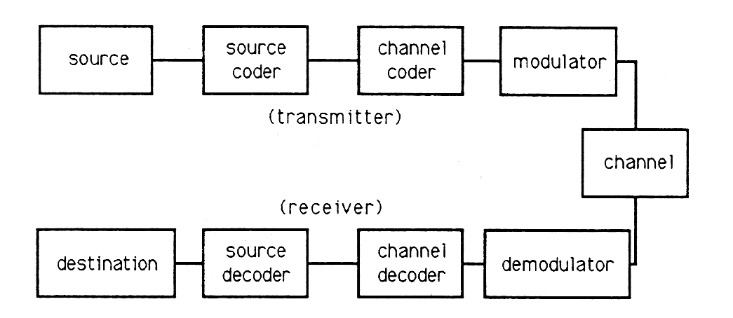
Figure 1 illustrates the basic building blocks that apply to any problem in the theory of (tele-) communication. The source is an arbitrary source of information. It can be the time-varying voltage at the output of a vibration sensor (such as an integrating accelerometer for measuring motion or a microphone for measuring sound pressure); it can be the charges stored in the CCD array of a solid-state camera; it can be the addresses generated from a sequence of keystrokes at a computer terminal; it can be a sequence of instructions in a computer program. The source coder is a device for turning primitive source outputs into more efficient representations. For example, in a recording studio, the source coder would convert analog voltages into digital approximations using an converter; a fancy source coder would use a fancy converter that finely quantized likely analog values and crudely quantized unlikely values. If the source is a source of discrete symbols like letters and numbers, then a fancy source code would assign short binary sequences to likely symbols (such as ) and long binary sequences to unlikely symbols (such as ). The channel coder adds “redundant bits” to the binary output of the source coder so that errors of transmission or storage may be detected and corrected. In the simplest example, a binary string of the form 01001001 would have an extra bit of 1 added to give even parity (an even number of l's) to the string; the string 10110111 would have an extra bit of 0 added to preserve the even parity . If one bit error is introduced in the channel, then the parity is odd and the receiver knows that an error has occurred. The modulator takes outputs of the channel coder, a stream of binary digits, and constructs an analog waveform that represents a block of bits. For example, in a 9600 baud Modem, five bits are used to determine one of phases that are used to modulate the signal . Each possible string of five bits has its own personalized phase, , and this phase can be determined at the receiver. The signal is an analog signal that may be transmitted over a channel (such as a telephone line, a microwave link, or a fiber-optic cable). The channel has a finite bandwidth, meaning that it distorts signals, and it is subject to noise or interference from other electromagnetic radiation. Therefore transmitted information arrives at the demodulator in imperfect form. The demodulator uses filters matched to the modulated signals to demodulate the phase and look up the corresponding bit stream. The channel decoder converts the coded bit stream into the information bit stream, and the source decoder looks up the corresponding symbol. This sequence of steps is illustrated symbolically in Figure 7.3.
![The is a sumbolic representation of communication. The image consist of a sequence of 0 and 1 patterns connected by arrows. The sequence starts at the upper left with a_i. An arrow proceeds to the right to 0110 then to 01100 and end the upper row with a_cos(ωt-φ[01100]). An arrow forms a right angle down and then another right angle to the left. The arrow then intersects φ then 01100 then 0110 and finally ends this bottom row at a_i.](/jc2012-war/ocw/mirror/col10685_1.2_complete/m21407/pic003.png)
In your subsequent courses on communication theory you will study each block of Figure 1 in detail. You will find that every source of information has a characteristic complexity, called entropy , that determines the minimum rate at which bits must be generated in order to represent the source. You will also find that every communication channel has a characteristic tolerance for bits, called channel capacity . This capacity depends on signal-to-noise ratio and bandwidth. When the channel capacity exceeds the source entropy, then you can transmit information reliably; if it does not, then you cannot.
Notification Switch
Would you like to follow the 'A first course in electrical and computer engineering' conversation and receive update notifications?

|
|

|
|

|
|

|
|

|
|

|
|

|
|

|
|

|
|

|