

| << Chapter < Page | Chapter >> Page > |
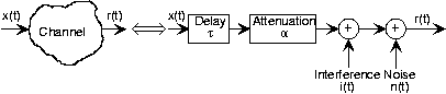
Both wireline and wireless channels share characteristics, allowing us to use a common model for how the channel affectstransmitted signals.
Is this model for the channel linear?
The additive-noise channel is not linear because it does not have the zero-input-zero-output property(even though we might transmit nothing, the receiver's input consists of noise).
As expected, the signal that emerges from the channel is corrupted, but does contain the transmittedsignal. Communication system design begins with detailing the channel model, then developing the transmitter and receiver thatbest compensate for the channel's corrupting behavior. We characterize the channel's quality by the signal-to-interferenceratio ( SIR ) and the signal-to-noise ratio ( SNR ). The ratios are computed according to the relative power of each within the transmitted signal's bandwidth . Assuming the signal 's spectrum spans the frequency interval , these ratios can be expressed in terms of power spectra.
Notification Switch
Would you like to follow the 'Fundamentals of electrical engineering i' conversation and receive update notifications?

|
|

|
|

|
|

|
|

|
|
|
|
|

|
|
|
|

|
|

|