

| << Chapter < Page | Chapter >> Page > |
We have found that the way to think about circuits is to locate and group parallel and series resistor combinations. Thoseresistors not involved with variables of interest can be collapsed into a single resistance. This result is known as an equivalent circuit : from the viewpoint of a pair of terminals, a group of resistors functions as a single resistor,the resistance of which can usually be found by applying the parallel and series rules.
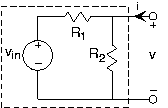
This result generalizes to include sources in a very interesting and useful way. Let's consider our simple attenuator circuit (shown in the figure ) from the viewpoint of the output terminals. We want to find the v-i relation for the output terminal pair, and then find the equivalent circuit for the boxed circuit. Toperform this calculation, use the circuit laws and element relations, but do not attach anything to the outputterminals. We seek the relation between and that describes the kind of element that lurks within the dashed box. The result is
If we consider the simple circuit of [link] , we find it has the v-i relation at its terminals of
For any circuit containing resistors and sources, the v-i relation will be of the form
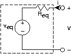
To be more specific, consider the equivalent circuit of this figure . Let the terminals be open-circuited, which has the effect of setting thecurrent to zero. Because no current flows through the resistor, the voltage across it iszero (remember, Ohm's Law says that ). Consequently, by applying KVL we have that the so-calledopen-circuit voltage equals the Thévenin equivalent voltage. Now consider the situation when we set the terminal voltage to zero(short-circuit it) and measure the resulting current. Referring to the equivalent circuit, the source voltage now appearsentirely across the resistor, leaving the short-circuit current to be . From this property, we can determine the equivalent resistance.
Notification Switch
Would you like to follow the 'Fundamentals of electrical engineering i' conversation and receive update notifications?

|
|

|
|

|
|

|
|

|
|

|
|

|
|

|
|

|
|
|
|
|

|