

| << Chapter < Page | Chapter >> Page > |
Our CDMA simulation will help users understand the basic concepts of CDMA and the effects of the various parameters on error rate. Our code is available for download here . The MATLAB code is based on this simple model of CDMA.
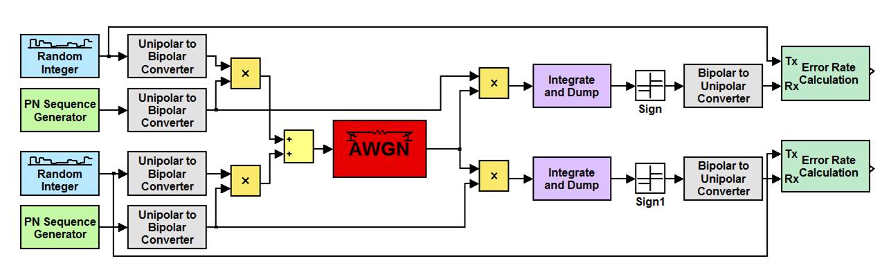
We initially used Simulink to model CDMA, but since each user requires their own random sequence and PN sequence, we had no easy way to add multiple users. We based the code for our MATLAB model off of the setup of our Simulink model.
The inputs to our MATLAB simulation are the processing gain, length of sequence to be transmited, signal-to-noise ratio (SNR) of our additive white Gaussian noise (AWGN) channel, number of users, and the degree of the generator polynomial of our MLSR, which affects the period of the PN sequence. Each user will transmit a data sequence of 0s and 1s, determined by a random number generator. These random sequences are determined independently. Each user will also be assigned to a distinct pseudo-random noise (PN) sequence of 0s and 1s. Since we are using a long spreading sequence, the PN sequence will be periodic with a period which is much longer than the processing gain. The generation of pseudo-random sequences will be discussed in a later section.
Each user’s data sequence must be modulated by a corresponding PN sequence, so we used a unipolar to bipolar converter to change the 0s and 1s of the data and PN sequences to -1s and 1s. To get the baseband waveform which will be transmitted, we take the product of the converted data and PN sequences. Since the idea of CDMA is for multiple users transmit information over a single channel, we sum the baseband waveforms of all of the users. Our simulation is conducted at baseband, so we will now send the accumulated sum of waveforms through the AWGN channel.
We are interested in the errors caused by the channel, so we need to compare the transmitted signals to the received signals. Since each user will experience approximately the same error rate, so we only need to demodulate the data for one user to estimate the bit error rate of our system. To demodulate, we multiply the received output of the channel by the PN sequence corresponding to the user whose sequence we want to receive. Then, we integrate and dump for each transmitted bit. Since the PN sequences are roughly orthogonal, integrating will isolate the waveform corresponding to the PN sequence we used to demodulate. Then, we can use the sign of the integration result to determine whether the received bit is -1 or 1. We can convert this result back to 0s and 1s with a bipolar to unipolar converter.
We determine the number of errors in our system by comparing the received and transmitted sequences. Going through both sequences bit by bit, we count an error whenever the two do not match.
Notification Switch
Would you like to follow the 'Elec 301 projects fall 2011' conversation and receive update notifications?

|
|

|
|

|
|

|
|
|
|
|
|
|
|

|
|

|
|
|
|
|

|