Find the Fourier transform of the following signals. Sketch the graph of the Fourier transform if it is real, otherwise, sketch the magnitude and phase fo the Fourier transform:
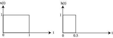
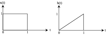
Find the convolution of the following pairs of signals:
Find the output of the filter whose transfer function is
and whose input is
. Hint, find the impulse response
corresponding to
and convolve it with the input.
Show that if
, then
Hint: Integrate both sides of
. Then express the right hand integral as the limit of a sum (as in a calculus textbook). Then by linearity, you can exchange the sum and the
.
Find an expression for the convolution of
and
Find an expression for the convolution of
and
.
Find the Fourier transform of the periodic signal in problem 2, Chapter 2.
Consider a filter having the impulse response
Sketch the frequency response (both magnitude and phase) of the filter and find the output of the filter when the input is
.
Repeat the previous problem for the impulse response given by
Suppose that two filters having impulse responses
and
are cascaded (i.e. connected in series). Find the impulse response of the equivalent filter assuming
and
.
Design a first-order lowpass filter having a corner frequency of 100 Hz. Use a
resistor. Plot both the magnitude and phase of the filter's frequency response.
Design a first-order highpass filter having a corner frequency of 1000 Hz. Use a
capacitor. Plot both the magnitude and phase of the filter's frequency response.
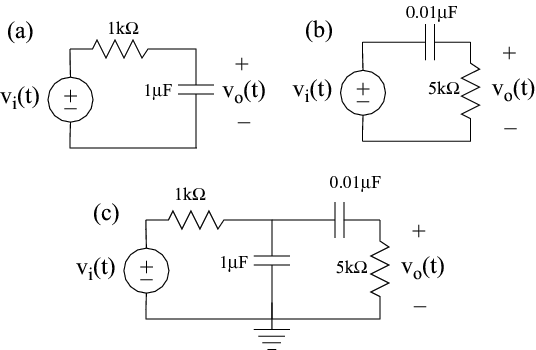
The following problems are associated with the circuits in
[link] :
Problem
[link] .
Find the frequency response of the circuit in
[link] (a), and sketch its magnitude and phase.
Find the frequency response of the circuit in
[link] (b) and sketch its magnitude and phase.
Find the frequency response of the filter in
[link] (c), sketch its magnitude and phase and show that it is not the product of the frequency responses for problems
[link] and
[link] .