

| << Chapter < Page | Chapter >> Page > |

The presence of a current source in the circuit does not affect the node method greatly; just include it in writing KCLequations as a current leaving the node. The circuit has three nodes, requiring us to define twonode voltages. The node equations are
Note that the node voltage corresponding to the node that we are writing KCL for enters with a positive sign,the others with a negative sign, and that the units of each term is given in amperes. Rewrite these equations in the standardset-of-linear-equations form. Solving these equations gives To find the indicated current, we simply use .

In this circuit ( [link] ), we cannot use the series/parallel combination rules: The vertical resistorat node 1 keeps the two horizontal 1 Ω resistors from being in series, and the 2 Ω resistor prevents the two1 Ω resistors at node 2 from being in series. We really do need the node method to solve this circuit! Despitehaving six elements, we need only define two node voltages. The node equations are Solving these equations yields and . The output current equals . One unfortunate consequence of using the element's numericvalues from the outset is that it becomes impossible to check units while setting up and solving equations.
What is the equivalent resistance seen by the voltagesource?
To find the equivalent resistance, we need to find the current flowing through the voltage source. This currentequals the current we have just found plus the current flowing through the other vertical 1 Ω resistor. Thiscurrent equals , making the total current through the voltage source (flowingout of it) .Thus, the equivalent resistance is .
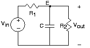
The node method applies to RLC circuits, without significant modification from the methods used on simple resistive circuits,if we use complex amplitudes. We rely on the fact that complex amplitudes satisfy KVL, KCL, and impedance-based v-i relations. In the example circuit, we define complex amplitudes for the input and output variables andfor the node voltages. We need only one node voltage here, and its KCL equation is with the result To find the transfer function between input and output voltages, we compute the ratio . The transfer function's magnitude and angle are This circuit differs from the one shown previously in that the resistor has been added across the output. What effect has it had on the transfer function, which in the original circuit was a lowpassfilter having cutoff frequency ? As shown in [link] , adding the second resistor has two effects: it lowers the gainin the passband (the range of frequencies for which the filter has little effect on the input) and increases the cutofffrequency.
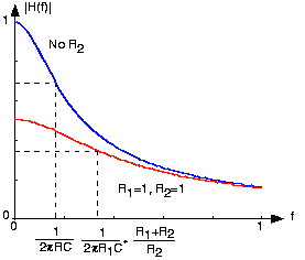
When , as shown on the plot, the passband gain becomes half of theoriginal, and the cutoff frequency increases by the same factor. Thus, adding provides a 'knob' by which we can trade passband gain for cutoff frequency.
We can change the cutoff frequency without affectingpassband gain by changing the resistance in the original circuit. Does the addition of the resistor help in circuit design?
Not necessarily, especially if we desire individual knobs for adjusting the gain and the cutoff frequency.
Notification Switch
Would you like to follow the 'Fundamentals of electrical engineering i' conversation and receive update notifications?

|
|

|
|

|
|
|
|
|

|
|

|
|

|
|

|
|

|
|

|
|

|