

| << Chapter < Page | Chapter >> Page > |
A first-order lowpass filter has the frequency response
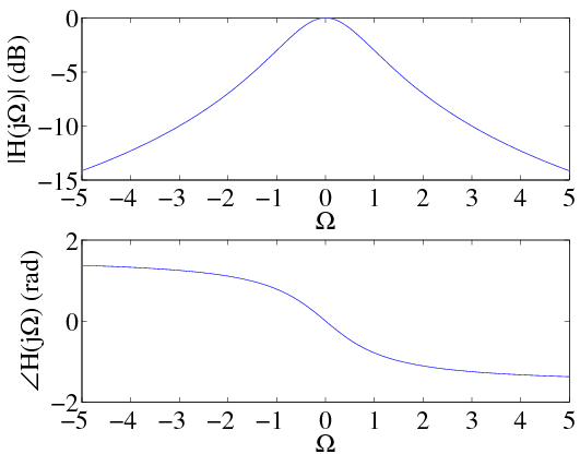
The frequency at which the frequency response magnitude has dropped to is called the corner frequency This term most likely originates from it's role in Bode plots, a shortcut method for sketching the graph of a frequency response. . The frequency response magnitude and phase are plotted in [link] . It is common to express the frequency response magnitude in units of decibels (dB) using the formula
At the corner frequency for a first order lowpass filter, the frequency response magnitude is or roughly -3 dB. From [link] , it can easily be seen that the impulse response for the first-order lowpass filter is given by
A first-order highpass filter is given by
Notice that
This makes sense since a highpass filter can be constructed by taking the filter input and subtracting from it a lowpass filtered version of . The impulse response of the first-order highpass filter therefore becomes:

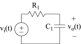
First order filters can be easily implemented using linear circuit elements like resistors, capacitors, and inductors. [link] shows a first order filter based on a resistor and a capacitor. Since the impedance for a resistor and capacitor are and , respectively, voltage division leads to a frequency response of
Therefore the corner frequency for this filter is . Similarly, a first-order highpass filter can be implemented using a resistor and capacitor as shown in [link] . This filter has a frequency response of
The corner frequency for the highpass filter is seen to be .

Now one might be tempted to apply the results of [link] to build a bandpass filter by cascading the lowhpass and highpass circuits in Figures [link] and [link] , respectively. Theory would predict that the equivalent frequency response of this circuit is given by
Unfortunately, this is not possible since the circuit elements in the lowpass and highpass filters interact with one another and therefore affect the overall behavior of the circuit. This interaction between the two circuits is called loading will be studied in greater detail in the exercises. To get theoretical behavior, it is necessary to use a voltage follower circuit, between the lowpass filter from the highpass circuits. The voltage follower circuit is usually an active circuit (requires external power supply) that has very high input impedance and very low output impedance. This eliminates any loading effects which would normally occur between the lowpass and highpass filter circuits.
Notification Switch
Would you like to follow the 'Signals, systems, and society' conversation and receive update notifications?

|
|

|
|

|
|

|
|

|
|

|
|

|
|

|
|

|
|

|