<< Chapter < Page Chapter >> Page >
This module summarizes the key concepts of transfer functions and includes examples of using transfer functions.

If the source consists of two (or more) signals, we know from linear system theory that the output voltage equalsthe sum of the outputs produced by each signal alone. In short, linear circuits are a special case of linear systems, andtherefore superposition applies. In particular, suppose these component signals are complex exponentials, each of which has afrequency different from the others. The transfer function portrays how the circuit affects the amplitude and phase of eachcomponent, allowing us to understand how the circuit works on a complicated signal. Those components having a frequency lessthan the cutoff frequency pass through the circuit with little modification while those having higher frequencies aresuppressed. The circuit is said to act as a filter , filtering the source signal based on the frequency of eachcomponent complex exponential. Because low frequencies pass through the filter, we call it a lowpass filter to express more precisely its function.

We have also found the ease of calculating the output forsinusoidal inputs through the use of the transfer function. Once we find the transfer function, we can write the output directlyas indicated by the output of a circuit for a sinusoidal input .
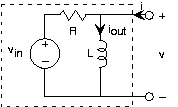
Rl circuit

Let's apply these results to a final example, in which the input is a voltage source and the output is the inductorcurrent. The source voltage equals V in 2 2 60 t 3 . We want the circuit to pass constant (offset) voltageessentially unaltered (save for the fact that the output is a current rather than a voltage) and remove the 60 Hz term.Because the input is the sum of two sinusoids--a constant is a zero-frequency cosine--our approach is

  1. find the transfer function using impedances;
  2. use it to find the output due to each input component;
  3. add the results;
  4. find element values that accomplish our design criteria.
Because the circuit is a series combination of elements, let's use voltage divider to find the transfer function between V in and V , then use the v-i relation of the inductor to find its current.
I out V in 2 f L R 2 f L 1 2 f L 1 2 f L R H f
where voltage divider 2 f L R 2 f L and inductor admittance 1 2 f L [Do the units check?] The formof this transfer function should be familiar; it is a lowpass filter, and it willperform our desired function once we choose element values properly.

The constant term is easiest to handle. The output is given by 3 H 0 3 R . Thus, the value we choose for the resistance will determinethe scaling factor of how voltage is converted into current. For the 60 Hz component signal, the output current is 2 H 60 2 60 t H 60 . The total output due to our source is

i out 2 H 60 2 60 t H 60 3 H 0
The cutoff frequency for this filter occurs when the real andimaginary parts of the transfer function's denominator equal each other. Thus, 2 f c L R , which gives f c R 2 L . We want this cutoff frequency to be much less than 60 Hz.Suppose we place it at, say, 10 Hz. This specification would require the component values to be related by R L 20 62.8 . The transfer function at 60 Hz would be
1 2 60 L R 1 R 1 6 1 1 R 1 37 0.16 1 R
which yields an attenuation (relative to the gain at zero frequency) of about 1 6 , and result in an output amplitude of 0.3 R relative to the constant term's amplitude of 3 R . A factor of 10 relative size between the two components seemsreasonable. Having a 100 mH inductor would require a 6.28 Ω resistor. An easily available resistor value is 6.8Ω; thus, this choice results in cheaply and easily purchased parts. To make the resistance bigger would require aproportionally larger inductor. Unfortunately, even a 1 H inductor is physically large; consequently low cutofffrequencies require small-valued resistors and large-valued inductors. The choice made here represents only onecompromise.

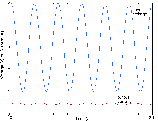
The phase of the 60 Hz component will very nearly be 2 , leaving it to be 0.3 R 2 60 t 2 0.3 R 2 60 t . The waveforms for the input and output are shown in [link] .
Waveforms

Input and output waveforms for the example R L circuit when the element values are R 6.28 and L 100 mH .

Note that the sinusoid's phase has indeed shifted; the lowpass filter not only reduced the 60 Hz signal's amplitude, but alsoshifted its phase by 90°.

Questions & Answers

what is biology
Hajah Reply
the study of living organisms and their interactions with one another and their environments
AI-Robot
what is biology
Victoria Reply
HOW CAN MAN ORGAN FUNCTION
Alfred Reply
the diagram of the digestive system
Assiatu Reply
allimentary cannel
Ogenrwot
How does twins formed
William Reply
They formed in two ways first when one sperm and one egg are splited by mitosis or two sperm and two eggs join together
Oluwatobi
what is genetics
Josephine Reply
Genetics is the study of heredity
Misack
how does twins formed?
Misack
What is manual
Hassan Reply
discuss biological phenomenon and provide pieces of evidence to show that it was responsible for the formation of eukaryotic organelles
Joseph Reply
what is biology
Yousuf Reply
the study of living organisms and their interactions with one another and their environment.
Wine
discuss the biological phenomenon and provide pieces of evidence to show that it was responsible for the formation of eukaryotic organelles in an essay form
Joseph Reply
what is the blood cells
Shaker Reply
list any five characteristics of the blood cells
Shaker
lack electricity and its more savely than electronic microscope because its naturally by using of light
Abdullahi Reply
advantage of electronic microscope is easily and clearly while disadvantage is dangerous because its electronic. advantage of light microscope is savely and naturally by sun while disadvantage is not easily,means its not sharp and not clear
Abdullahi
cell theory state that every organisms composed of one or more cell,cell is the basic unit of life
Abdullahi
is like gone fail us
DENG
cells is the basic structure and functions of all living things
Ramadan
What is classification
ISCONT Reply
is organisms that are similar into groups called tara
Yamosa
in what situation (s) would be the use of a scanning electron microscope be ideal and why?
Kenna Reply
A scanning electron microscope (SEM) is ideal for situations requiring high-resolution imaging of surfaces. It is commonly used in materials science, biology, and geology to examine the topography and composition of samples at a nanoscale level. SEM is particularly useful for studying fine details,
Hilary
cell is the building block of life.
Condoleezza Reply
Got questions? Join the online conversation and get instant answers!
Jobilize.com Reply

Get Jobilize Job Search Mobile App in your pocket Now!

Get it on Google Play Download on the App Store Now


Source:  OpenStax, Fundamentals of electrical engineering i. OpenStax CNX. Aug 06, 2008 Download for free at http://legacy.cnx.org/content/col10040/1.9
Google Play and the Google Play logo are trademarks of Google Inc.

Notification Switch

Would you like to follow the 'Fundamentals of electrical engineering i' conversation and receive update notifications?

Ask