<< Chapter < Page Chapter >> Page >
This module summarizes the key concepts of transfer functions and includes examples of using transfer functions.

If the source consists of two (or more) signals, we know from linear system theory that the output voltage equalsthe sum of the outputs produced by each signal alone. In short, linear circuits are a special case of linear systems, andtherefore superposition applies. In particular, suppose these component signals are complex exponentials, each of which has afrequency different from the others. The transfer function portrays how the circuit affects the amplitude and phase of eachcomponent, allowing us to understand how the circuit works on a complicated signal. Those components having a frequency lessthan the cutoff frequency pass through the circuit with little modification while those having higher frequencies aresuppressed. The circuit is said to act as a filter , filtering the source signal based on the frequency of eachcomponent complex exponential. Because low frequencies pass through the filter, we call it a lowpass filter to express more precisely its function.

We have also found the ease of calculating the output forsinusoidal inputs through the use of the transfer function. Once we find the transfer function, we can write the output directlyas indicated by the output of a circuit for a sinusoidal input .

Rl circuit

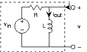
Let's apply these results to a final example, in which the input is a voltage source and the output is the inductorcurrent. The source voltage equals V in 2 2 60 t 3 . We want the circuit to pass constant (offset) voltageessentially unaltered (save for the fact that the output is a current rather than a voltage) and remove the 60 Hz term.Because the input is the sum of two sinusoids--a constant is a zero-frequency cosine--our approach is

  1. find the transfer function using impedances;
  2. use it to find the output due to each input component;
  3. add the results;
  4. find element values that accomplish our design criteria.
Because the circuit is a series combination of elements, let's use voltage divider to find the transfer function between V in and V , then use the v-i relation of the inductor to find its current.
I out V in 2 f L R 2 f L 1 2 f L 1 2 f L R H f
where voltage divider 2 f L R 2 f L and inductor admittance 1 2 f L [Do the units check?] The formof this transfer function should be familiar; it is a lowpass filter, and it willperform our desired function once we choose element values properly.

The constant term is easiest to handle. The output is given by 3 H 0 3 R . Thus, the value we choose for the resistance will determinethe scaling factor of how voltage is converted into current. For the 60 Hz component signal, the output current is 2 H 60 2 60 t H 60 . The total output due to our source is

i out 2 H 60 2 60 t H 60 3 H 0
The cutoff frequency for this filter occurs when the real andimaginary parts of the transfer function's denominator equal each other. Thus, 2 f c L R , which gives f c R 2 L . We want this cutoff frequency to be much less than 60 Hz.Suppose we place it at, say, 10 Hz. This specification would require the component values to be related by R L 20 62.8 . The transfer function at 60 Hz would be
1 2 60 L R 1 R 1 6 1 1 R 1 37 0.16 1 R
which yields an attenuation (relative to the gain at zero frequency) of about 1 6 , and result in an output amplitude of 0.3 R relative to the constant term's amplitude of 3 R . A factor of 10 relative size between the two components seemsreasonable. Having a 100 mH inductor would require a 6.28 Ω resistor. An easily available resistor value is 6.8Ω; thus, this choice results in cheaply and easily purchased parts. To make the resistance bigger would require aproportionally larger inductor. Unfortunately, even a 1 H inductor is physically large; consequently low cutofffrequencies require small-valued resistors and large-valued inductors. The choice made here represents only onecompromise.

The phase of the 60 Hz component will very nearly be 2 , leaving it to be 0.3 R 2 60 t 2 0.3 R 2 60 t . The waveforms for the input and output are shown in [link] .

Waveforms

Input and output waveforms for the example R L circuit when the element values are R 6.28 and L 100 mH .

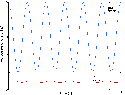
Note that the sinusoid's phase has indeed shifted; the lowpass filter not only reduced the 60 Hz signal's amplitude, but alsoshifted its phase by 90°.

Questions & Answers

calculate molarity of NaOH solution when 25.0ml of NaOH titrated with 27.2ml of 0.2m H2SO4
Gasin Reply
what's Thermochemistry
rhoda Reply
the study of the heat energy which is associated with chemical reactions
Kaddija
How was CH4 and o2 was able to produce (Co2)and (H2o
Edafe Reply
explain please
Victory
First twenty elements with their valences
Martine Reply
what is chemistry
asue Reply
what is atom
asue
what is the best way to define periodic table for jamb
Damilola Reply
what is the change of matter from one state to another
Elijah Reply
what is isolation of organic compounds
IKyernum Reply
what is atomic radius
ThankGod Reply
Read Chapter 6, section 5
Dr
Read Chapter 6, section 5
Kareem
Atomic radius is the radius of the atom and is also called the orbital radius
Kareem
atomic radius is the distance between the nucleus of an atom and its valence shell
Amos
Read Chapter 6, section 5
paulino
Bohr's model of the theory atom
Ayom Reply
is there a question?
Dr
when a gas is compressed why it becomes hot?
ATOMIC
It has no oxygen then
Goldyei
read the chapter on thermochemistry...the sections on "PV" work and the First Law of Thermodynamics should help..
Dr
Which element react with water
Mukthar Reply
Mgo
Ibeh
an increase in the pressure of a gas results in the decrease of its
Valentina Reply
definition of the periodic table
Cosmos Reply
What is the lkenes
Da Reply
what were atoms composed of?
Moses Reply
Got questions? Join the online conversation and get instant answers!
Jobilize.com Reply

Get Jobilize Job Search Mobile App in your pocket Now!

Get it on Google Play Download on the App Store Now


Source:  OpenStax, Fundamentals of electrical engineering i. OpenStax CNX. Aug 06, 2008 Download for free at http://legacy.cnx.org/content/col10040/1.9
Google Play and the Google Play logo are trademarks of Google Inc.

Notification Switch

Would you like to follow the 'Fundamentals of electrical engineering i' conversation and receive update notifications?

Ask