

| << Chapter < Page | Chapter >> Page > |
Signals are manipulated by systems .Mathematically, we represent what a system does by the notation , with representing the input signal and the output signal.
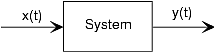
This notation mimics the mathematical symbology of a function: A system's input is analogous to an independentvariable and its output the dependent variable. For the mathematically inclined, a system is a functional : a function of a function (signals are functions).
Simple systems can be connected together--one system's outputbecomes another's input--to accomplish some overall design. Interconnection topologies can be quite complicated, butusually consist of weaves of three basic interconnection forms.
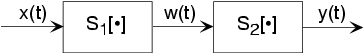
The simplest form is when one system's output is connected onlyto another's input. Mathematically, , and , with the information contained in processed by the first, then the second system. In some cases, the ordering of the systems matter, in others it does not. Forexample, in the fundamental model of communication the ordering most certainly matters.
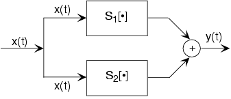
A signal is routed to two (or more) systems, with this signal appearing as the input to all systems simultaneously and with equalstrength. Block diagrams have the convention that signals going to more than one system are not split into pieces alongthe way. Two or more systems operate on and their outputs are added together to create the output . Thus, , and the information in is processed separately by both systems.
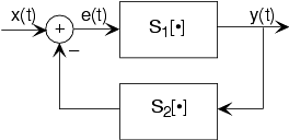
The subtlest interconnection configuration has a system's output also contributing to its input. Engineers would say theoutput is "fed back" to the input through system 2, hence the terminology. The mathematical statement of the feedback interconnection is that the feed-forward system produces the output: . The input equals the input signal minus the output of some other system's output to : . Feedback systems are omnipresent in control problems, with theerror signal used to adjust the output to achieve some condition defined by the input (controlling) signal. Forexample, in a car's cruise control system, is a constant representing what speed you want, and is the car's speed as measured by a speedometer. In thisapplication, system 2 is the identity system (output equals input).
Notification Switch
Would you like to follow the 'Fundamentals of electrical engineering i' conversation and receive update notifications?

|
|

|
|

|
|

|
|

|
|

|
|

|
|

|
|

|
|

|