

| << Chapter < Page | Chapter >> Page > |
Appendix V
Analysis of Polysilicon emitter BJT .
In Polysilicon emitter BJT (PET), a polycrystalline Si Film lies between Metallic Emitter Contact and Silicon Proper. By ion-implantation, the Polycrystalline Silicon Film is doped with Donor Arsenic Ions. By subsequent annealing, shallow diffusion of Donor Arsenic atoms from N + Poly-Silicon Source takes place leading to a shallow layer of N + in Si proper contacted by a similarly doped N + Poly-Silicon thin film. This structure is known as Polysilicon emitter BJT.
This is suitable for shallow EB Junction;
Compatible with self-aligned processing. This minimizes parasitic Resistance and Capacitances leading to faster response time.
Short Circuit Current Gain (β F ) in PET is considerably improved as compared to that of shallow all crystalline emitter of equivalent thickness.
The physics of improvement of Short Circuit Current Gain (β F ) in PET.

Figure V.1. Minority Carrier Concentration in a shallow EB Junction case 1. All pure single crystal structure and case 2 in Poly Si Emitter BJT.
Since W E <<L pE , therefore there is negligible recombination through out the Emitter. At the interface of Poly Si(region 1) and Pure Si(Region 2), continuity of carrier concentration and continuity of diffusion current requires that:


Therefore carrier concentration gradient in poly Si region is several times the carrier concentration gradient in Pure Silicon Emitter because mobility of hole in Pure Single Crystal Silicon region is several times greater than that in Poly Si on account of domain scattering in Poly region. Hence hole current crossing EB junction into Emitter is considerably reduced leading to a near unity Injection Efficiency. This leads to a much better α and hence a much better β . Now doping of base can be increased leading to a reduced base spreading resistance and hence better Figure of Merit and better Frequency Response without losing on current gain.
Process Steps of Poly Si Emitter BJT US Patent5736447. (P + NP)
www.patentsform.us/patents/5736447/fulltext.html
Step 1. Ion-Implantation of N type Base in P type substrate. Base Region is in space-apart relationship to the collector region.

Step 2. Stripping of exposed KPR layer(104) and deposition of FIRST Insulation Layer.

Step 3. Etching out of Emitter Contact Hole. The oxide film (108) is first isotropically etched and then anisotropically etched or we could do anisotropic etching directly

Step 4.Deposition of first conducting layer of thickness 500 to 2000 Angstrom. The first conducting layer is Poly-Silicon layer or in-situ polySi. P-type impurities namely Boron Ions are Ion-Implanted into the first conducting layer. Ion-Implantation energy is 50 to 100keV and the dose is 2×10 15 - 6×10 17 ions/cm 2 . Ion-implanted poly-Si layer acts as the source for shallow diffusion of P-type impurities in N-type Base to form a shallow self aligned Emitter in Pure Single Crystal Silicon Substrate. This shallow diffusion is achieved by rapid thermal annealing(RTA) at a temperature above 600ºC in a nitrogen atmosphere at a temperature of 800ºC - 950ºC.

Step 5. Base and Collector contact holes etched out in first conducting layer(110) and in first insulating layer(108) to Base(106) and to Collector(102). This is achieved by isotropic and then anisotropic etching or only by anisotropic etching.
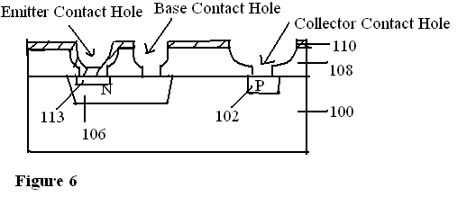
Step 6. Second Conducting Layer is deposited over 110 and to fill the contact holes at Emitter, Base and Collector. It may be Poly-Si or poly-Si in-situ or Metal Silicide. Second Conducting layer plus underlying conducting layer are patterned into Emitter Contact Pad, Base Contact Pad and Collector Contact Pad.

Directly quoted from the Patent:
“The above-described method of the present invention results in a BJT having a thin or shallow emitter region 113 which effectively minimizes the base-emitter junction capacitance, without the need for additional photolithographic steps required by the presently available technology. In this regard, the polysilicon emitter 112 is formed simultaneously with the patterning of the first and second conductive layers and is self –aligned with the resultant emitter contact. Moreover the necessity of the oxide layer 38 of the conventional method for manufacturing a BJT is eliminated. Hence this method is less complex and less costly than the conventional method”.
Notification Switch
Would you like to follow the 'Solid state physics and devices-the harbinger of third wave of civilization' conversation and receive update notifications?

|
|

|
|

|
|

|
|

|
|

|
|

|
|

|
|

|
|

|