

| << Chapter < Page | Chapter >> Page > |
Questions or comments concerning this laboratory should be directedto Prof. Charles A. Bouman, School of Electrical and Computer Engineering, Purdue University, West Lafayette IN 47907;(765) 494-0340; bouman@ecn.purdue.edu
This is the second part of a two week laboratory in digital filter design.The first week of the laboratory covered some basic examplesof FIR and IIR filters, and then introduced the concepts of filter design.In this week we will cover more systematic methods of designing both FIR and IIR filters.
Download DTFT.m for the following section.
We can generalize the idea of truncation by using different windowing functions to truncate anideal filter's impulse response. Note that by simply truncating the ideal filter's impulse response, we are actuallymultiplying (or “windowing”) the impulse response by a shifted function. This particular type of window is called a rectangular window. In general, the impulse reponse of the designed filter is related to the impulse response of the ideal filter by the relation
where is an -point window. We assume that
where is the cutoff frequency and is the desired window length.
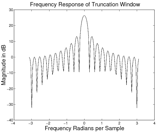
The rectangular window is defined as
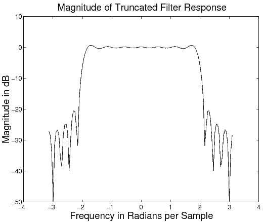
The DTFT of for is shown in [link] . The rectangular window is usually not preferredbecause it leads to the large stopband and passband ripple as shown in [link] .
More desirable frequency characteristics can be obtained by making a better selection for the window, . In fact, a variety of raised cosine windowsare widely used for this purpose. Some popular windows are listed below.
hann(N) ):
In filter design using different truncation windows, there are two key frequency domain effects that are important to the design: the transitionband roll-off , and the passband and stopband ripple (see [link] below). There are two corresponding parameters in the spectrum of each type ofwindow that influence these filter parameters. The filter's roll-off is related tothe width of center lobe of the window's magnitude spectrum. The ripple is influenced by the ratio of the mainlobe amplitude to the first sidelobe amplitude (or difference if using a dB scale).These two window spectrum parameters are not independent, and you should see a trend as you examine the spectra for different windows.The theoretical values for the mainlobe width and the peak-to-sidelobe amplitude are shown in [link] .
| Window (length N) | Mainlobe width | Peak-to-sidelobe amplitude (dB) |
Notification Switch
Would you like to follow the 'Purdue digital signal processing labs (ece 438)' conversation and receive update notifications?

|
|

|
|

|
|

|
|

|
|
|
|
|

|
|

|
|
|
|
|

|