

| << Chapter < Page | Chapter >> Page > |
Designing IIR filters is also straightforward. For example,the code
[b,a]=cheby1(10,5,0.25); designs a 10th order lowpass filter with 5 dB of ripple in the
passband, which extends from DC to 0.25 times the Nyquist rate.
While commands such as
firpm and
cheby1 make filter
design easy, be warned—strange things can happen,even to nice filters. Whenever using any of the filter design tools, always check
freqz(b,a) to verify that the
output of the design behaves as anticipated.There are many other ways to design LTI filters, and
M
atlab includes several commands that design filter coefficients:
cfirpm ,
firls ,
fir1 ,
fir2 ,
butter ,
cheby2 , and
ellip .
The subject of filter design is vast, and each of theseis useful in certain applications. For simplicity,
we have chosen to present most examples throughout
Software Receiver Design by using
firpm .
Rerun
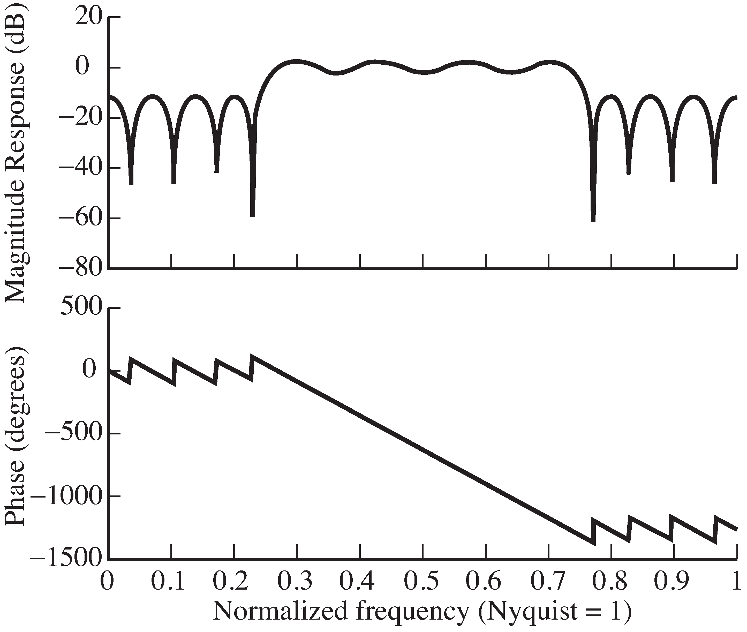
bandex.m with very narrow transition regions,
for instance
fbe =[0, 0.24, 0.2401, 0.6, 0.601, 1]. What happens to theripple in the passband? Compare the minimum magnitude in the passband
with the maximum value in the stopband.
Returning to the filter specified in
[link] ,
try using different numbers of terms in the impulse response,
fl= 5, 10, 100, 500, 1000. Comment on the resulting designs
in terms of flatness of the frequency response in the passband,attenuation from the passband to the stopband,
and the width of the transition band.
Specify and design a lowpass filter with cutoff
at
. What values of
fl ,
fbe , and
damps work best?
Specify and design a filter that has two passbands, one between [0.2, 0.3] and another between [0.5 0.6].
What values of
fl ,
fbe , and
damps work best?
Use the filter designed in
bandex.m to filter a white
noise sequence (generated by
randn )
using the time domain method from
waystofilt.m .
Verify that the output has a bandpass spectrum.
The preceding filter designs do not explicitly require the sampling rate of the signal. However, since the sampling rate determinesthe Nyquist rate, it is used implicitly. The next exercise asks that you familiarize yourself with “real” units of frequencyin the filter design task.
In Exercise
[link] , the program
specgong.m was used to analyze the sound of an Indonesian gong.
The three most prominent partials (or narrowband components)were found to be at about 520, 630, and 660 Hz.
firpm that will remove the two highest
partials from this sound without affecting the lowest partial.filter command to process the
gong.wav file
with your filter.sound command. Comment on what you hear.The next set of problems examines how accurate digital filters really are.
With a sampling rate of 44100 Hz, let
be a sinusoid
of frequency 3000 Hz. Design a lowpass filter with a cutofffrequency
fl of 1500 Hz, and let
be the output of the filter.
without using the
filter command (implement the filtering, using the
time domain method in
waystofilt.m ).
With the same setup as in Exercise [link] , generate as a bandlimited noise signal containing frequencies between 3000 Hz and the Nyquist rate.
fl of 1500 Hz.
How much does the filter attenuate the signal?Let the output of a LTI system be created from the input according to the formula
where is a small constant. This is drawn in [link] .
The effect of bandpass filtering can be accomplished by
Repeat the task given in Exercise [link] (the Indonesian gong filter design problem) by modulating with a 520 Hz cosine, lowpass filtering,and then remodulating. Compare the final output of this method with the direct bandpass filter design.
Here are some of our favorite books on signal processing:
Notification Switch
Would you like to follow the 'Software receiver design' conversation and receive update notifications?

|
|

|
|

|
|

|
|

|
|

|
|

|
|

|
|

|
|

|