

| << Chapter < Page | Chapter >> Page > |
From the definition of the Z-transform, a change of variable shows that a delay of samples in the time domain is equivalent to multiplication by in the Z-transform domain.
We may use this fact to re-write [link] in the Z-transform domain, by taking Z-transforms of both sides ofthe equation:
From this formula, we see that any filter which can be represented by a linear difference equation with constant coefficientshas a rational transfer function (i.e. a transfer function which is a ratio of polynomials).From this result, we may compute the frequency response of the filter by evaluating on the unit circle:
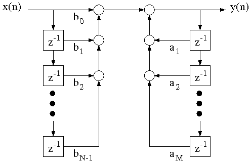
There are many different methods for implementing a general recursive difference equation of the form [link] . Depending on the application, some methods may be more robustto quantization error, require fewer multiplies or adds, or require less memory. [link] shows a system diagram known as the direct form implementation; it works for any discrete-time filterdescribed by the difference equation in [link] . Note that the boxes containing the symbol represent unit delays, while a parameter written next to a signal path represents multiplication by that parameter.
Download the files, nspeech1.mat and DTFT.m for the following section.
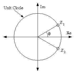
To illustrate the use of zeros in filter design, you will design a simple second order FIR filterwith the two zeros on the unit circle as shown in [link] . In order for the filter's impulse response to be real-valued,the two zeros must be complex conjugates of one another:
where is the angle of relative to the positive real axis. We will see later that may be interpreted as the location of the zeros in the frequency response.
The transfer function for this filter is given by
Use this transfer function to determine the difference equation for this filter.Then draw the corresponding system diagram and compute the filter's impulse response .
This filter is an FIR filter because it has impulse response of finite duration. Any filter with only zeros and no poles other than thoseat 0 and is an FIR filter. Zeros in the transfer function represent frequencies that arenot passed through the filter. This can be useful for removing unwanted frequencies in a signal.The fact that has zeros at implies that . This means that the filter will not pass pure sine waves at a frequencyof .
Use Matlab to compute and plot the magnitude of the filter's frequency response as a function of on the interval , for the following three values of :
Notification Switch
Would you like to follow the 'Purdue digital signal processing labs (ece 438)' conversation and receive update notifications?

|
|

|
|

|
|

|
|

|
|
|
|
|

|
|

|
|

|
|

|