

| << Chapter < Page | Chapter >> Page > |
Tension in the rope must equal the weight of the supported mass, as we can prove using Newton’s second law. If the 5.00-kg mass in the figure is stationary, then its acceleration is zero, and thus . The only external forces acting on the mass are its weight and the tension supplied by the rope. Thus,
where and are the magnitudes of the tension and weight and their signs indicate direction, with up being positive here. Thus, just as you would expect, the tension equals the weight of the supported mass:
For a 5.00-kg mass, then (neglecting the mass of the rope) we see that
If we cut the rope and insert a spring, the spring would extend a length corresponding to a force of 49.0 N, providing a direct observation and measure of the tension force in the rope.
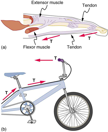
Flexible connectors are often used to transmit forces around corners, such as in a hospital traction system, a finger joint, or a bicycle brake cable. If there is no friction, the tension is transmitted undiminished. Only its direction changes, and it is always parallel to the flexible connector. This is illustrated in [link] (a) and (b).
Calculate the tension in the wire supporting the 70.0-kg tightrope walker shown in [link] .
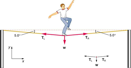
Strategy
As you can see in the figure, the wire is not perfectly horizontal (it cannot be!), but is bent under the person’s weight. Thus, the tension on either side of the person has an upward component that can support his weight. As usual, forces are vectors represented pictorially by arrows having the same directions as the forces and lengths proportional to their magnitudes. The system is the tightrope walker, and the only external forces acting on him are his weight and the two tensions (left tension) and (right tension), as illustrated. It is reasonable to neglect the weight of the wire itself. The net external force is zero since the system is stationary. A little trigonometry can now be used to find the tensions. One conclusion is possible at the outset—we can see from part (b) of the figure that the magnitudes of the tensions and must be equal. This is because there is no horizontal acceleration in the rope, and the only forces acting to the left and right are and . Thus, the magnitude of those forces must be equal so that they cancel each other out.
Whenever we have two-dimensional vector problems in which no two vectors are parallel, the easiest method of solution is to pick a convenient coordinate system and project the vectors onto its axes. In this case the best coordinate system has one axis horizontal and the other vertical. We call the horizontal the -axis and the vertical the -axis.
Notification Switch
Would you like to follow the 'Newton's laws' conversation and receive update notifications?

|
|

|
|

|
|

|
|

|
|

|
|

|
|

|
|

|
|

|