

| << Chapter < Page | Chapter >> Page > |
Portland Cement is manufactured by heating calcium carbonate and clay or shale in a kiln. During this process the calcium carbonate is converted to calcium oxide (also known as lime) and the clay minerals decompose to yield dicalcium silicate (Ca 2 SiO 4 , C2S) and other inorganic oxides such as aluminate and ferrite. Further heating melts the aluminate and ferrite phases. The lime reacts with dicalcium silicate to from tricalcium silicate (Ca 3 SiO 5 , C3S). As the mixture is cooled, tricalcium aluminate (Ca 3 Al 2 O 6 , C3A) and tetracalcium aluminoferrite (Ca 4 Al n Fe 2-n O 7 , C4AF) crystallize from the melt and tricalcium silicate and the remaining dicalcium silicate undergo phase transitions. These four minerals (C3S, C2S, C3A, and C4AF) comprise the bulk of most cement mixtures. Initially Portland cement production was carried out in a furnace, however, technological developments such as the rotary kiln have enhanced production capabilities and allowed cement to become one of the most widely used construction materials.
Cement plants generally produce various grades of cement by two processes, referred to as either the wet or dry process. The dry process uses a pneumatic kiln system which uses superheated air to convert raw materials to cement, whereas the wet process slurries the raw materials in water in preparation for conversion to cement. Cement manufacturers due to its higher energy efficiency generally favor the dry process, but the wet process tends to produce cement with properties more palatable to the energy services industry. The American Petroleum Institute (API) Class H cement used in energy service applications is produced by the wet process, and thus will be the focus of the following discussion.
The cement manufacturing process begins at the quarry ( [link] ), where limestone formations are ripped and crushed in two crushers to a mean particle size of 4". The quarry formation is not entirely limestone, and no attempt is made to isolate the limestone from the other minerals. On the contrary, the rippers act to blend in the “impurity” minerals as evenly as is feasible while still maintaining an acceptable limestone content so as not to “waste” the formation. This is accomplished by ripping the formation face at a 45° ( [link] ). The rock is quality controlled via mobile X-ray fluorescence (XRF) spectroscopy ( [link] ) at the starting point of a mobile covered conveyor belt system ( [link] ), which transports the material to a dome storage unit ( [link] ).


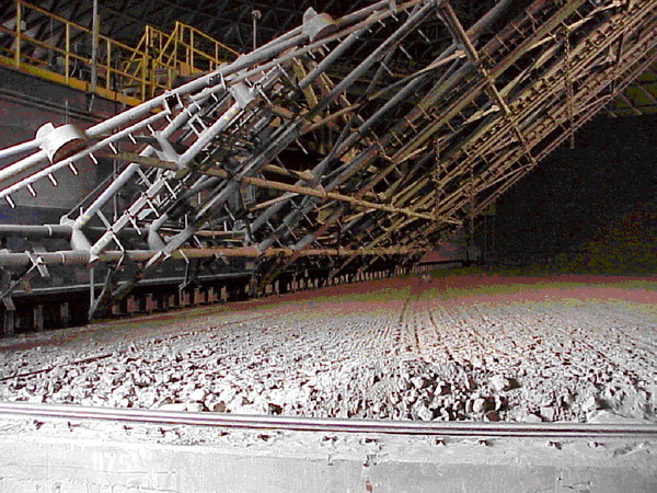
The dome storage unit has a capacity of 60 kilotons, and is filled by dispensing the rock from the conveyor at the top of the dome into a pile built in a circular pattern ( [link] ). The rock is reclaimed from storage via a raking device ( [link] ) that grates over the pile at the natural angle of material slide. The raked material slides to the base of the raking unit, where a second conveyor system transfers material to either of two limestone buffer bins ( [link] ), each of which is dedicated to a particular kiln process. There is an additional buffer bin for mill scale from a nearby steel plant, as well as a buffer bin for sand. It is worth noting at this point that the mill scale from the steel plant contains significant levels of boron, which acts as an innate retarder and seems to affect adversely, though not overly severely, the early compressive strength development when compared to cement from other plants.


Material leaving the buffer bins is monitored for elemental composition via XRF and feed rates are adjusted for maintaining proper flow of calcium, silicon, aluminum, and iron. The raw materials are carried to ball mills ( [link] ) for grinding to fine powder, which is then mixed with water. The resulting slurry is then sent to the rotary kiln for burning ( [link] ), or transformation into cement clinker.


The kilns are fired to an internal material temperature of 2700 °F ( [link] ) with a fuel of finely ground coal, natural gas, and/or various waste materials. Around fifty percent of the energy expenditure in the wet kiln process is dedicated to evaporating the water from the slurry, in contrast to the dry process, which spends most of its energy on the calcining process. Since the dry process only requires approximately half the energy of the wet process, it is generally more attractive to cement manufacturers. Unfortunately, the dry process in current use produces poor API Class H cement. A fuller understanding of the differences in cement synthesis via the two processes could lead to the development of a more effective dry synthesis of Class H cements, but that is beyond the scope of this work.

After the clinker leaves the kiln, it enters a cooler that uses pressurized air to cool the clinker. The energy absorbed by the air in the cooler serves to pre-heat the air for feed into the kiln. The cooled clinker is then taken to storage to await final grinding with approximately five percent gypsum by weight. After grinding to the specified fineness, the final cement powder is pneumatically transferred to storage silos until it is shipped to the customer.
Quality control of the clinker and final powder is handled via an automated X-ray diffraction/X-ray fluorescence (XRD/XRF) system, simple wet chemical analyses, simple optical microscopy, and periodic performance tests, including compressive strength and thickening time. This entire process results in the heterogeneous nanocomposite of calcium silicate and aluminate particles, among other materials, which make up a typical cement grain.
Notification Switch
Would you like to follow the 'Portland cement in the energy industry' conversation and receive update notifications?

|
|

|
|

|
|

|
|

|
|

|
|

|
|

|
|

|
|

|