

| << Chapter < Page | Chapter >> Page > |
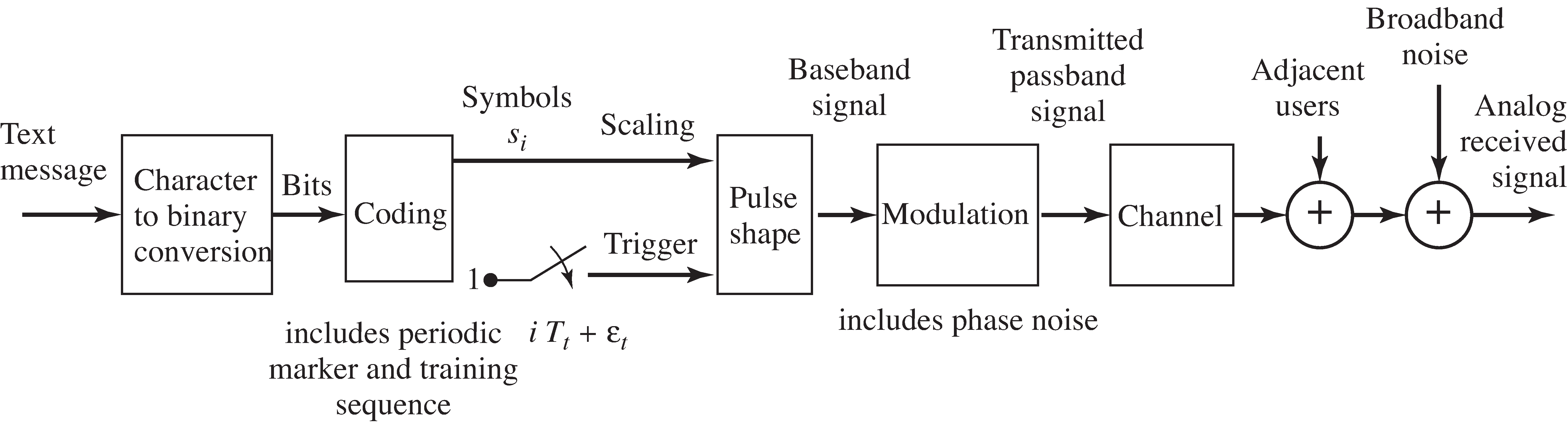
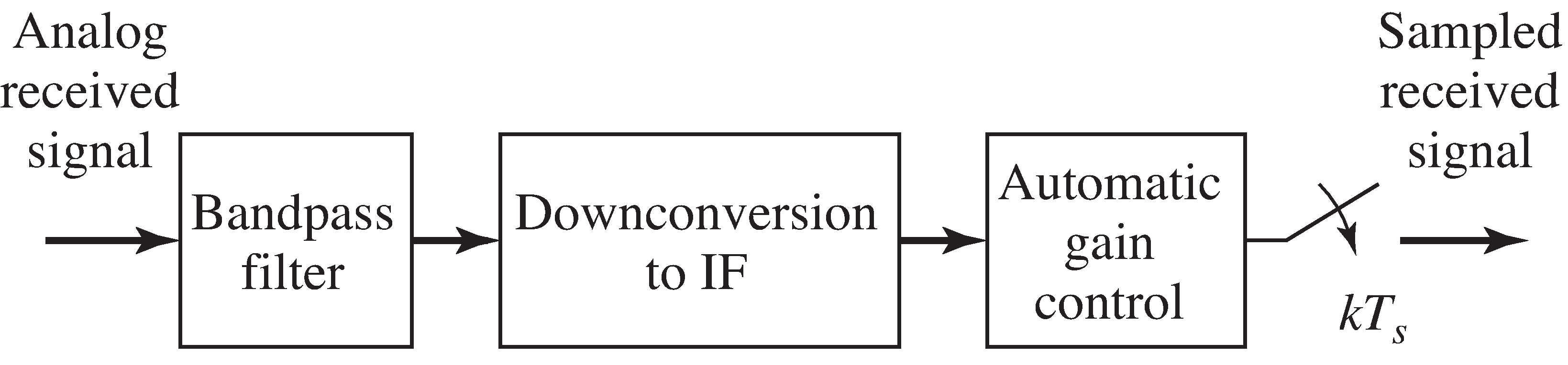
This section describes the construction of the sampled IF signal that must be processed by the receiver. The system that generatesthe analog received signal is shown in block diagram form in [link] . The front end of the receiver that turns thisinto a sampled IF signal is shown in [link] .
The original message in
[link] is a character string of English text.
Each character is converted into a 7-bit binary stringaccording to the ASCII conversion format (e.g., the letter “a” is
1100001 and the letter “M” is 1001101), as inExample
[link] .
The bit string is coded using the (5,2) linear block codespecified in
blockcode52.m which associates a 5-bit
code with each pair of bits. The output of the block codeis then partitioned into pairs that
are associated with the four integers of a 4-PAM alphabet
and
via the mapping
as in Example
[link] .
Thus, if there are
letters, there are
(uncoded) bits,
coded bits,
and
4-PAM symbols.
These mappings are familiar from
[link] ,
and are easy to use with the help of the M
atlab functions
bin2text.m and
text2bin.m .
Exercise
[link] provides several
hints to help implementthe
encoding, and the M
atlab function
nocode52.m outlines the necessary transformations
from the original text into a sequence of 4-PAMsymbols
.
In order to decode the message at the receiver, the recovered symbols must be properly grouped and the start ofeach group must be located. To aid this frame synchronization, a marker sequenceis inserted in the symbol stream at the start of every block of 100 letters (at the start of every 875 symbols).The header/training sequence that starts each frame is given by the phrase
which codes into 245 4-PAM symbols and is assumed to be known at the receiver.This marker text string can be used as a training sequence by the adaptive equalizer.The unknown message begins immediately after each training segment. Thus, the symbol stream is a coded message periodically interrupted by the same marker/training clump.
As indicated in [link] , pulses are initiated at intervals of seconds, and each is scaled by the 4-PAM symbol value.This translates the discrete-time symbol sequence (composed of the coded message interleaved with the marker/training segments)into a continuous-time signal
The actual transmitter symbol period is required to be within percent of a nominal symbol period microseconds. The transmitter symbol period clock is assumed to besteady enough that the timing offset and its period are effectively time-invariant over the duration of a single frame.
Details of the transmission specifications are given in [link] . The pulse-shaping filter is a square-root raised cosine filter symmetrically truncated to eight symbol periods.The rolloff factor of the pulse-shaping filter is fixed within some range and is known at the receiver,though it could take on different values with different transmissions.The (half-power) bandwidth of the square-root raised cosine pulse could be as large as 102 kHz for the nominal . With double sideband modulation, the pulse shape bandwidthdoubles so that each passband FDM signal will need a bandwidth at least 204 kHz wide.
Notification Switch
Would you like to follow the 'Software receiver design' conversation and receive update notifications?

|
|

|
|

|
|

|
|

|
|

|
|
|
|
|
|
|
|

|
|

|