Signals normally pass through interconnections of subsystems.
Feedback provides an opportunity to use and to integrate material we have learned (Laplace transform, frequency response, step response) in an important application area.Stability is an important issue with feedback systems.
Unstable systems can be stabilized with feedback.
Lecture #12:
INTERCONNECTED SYSTEMS AND FEEDBACK
Motivation:
Signals normally pass through interconnections of subsystems.
Feedback is widely used in both man-made and natural systems to enhance performance.
Feedback provides an opportunity to use and to integrate material we have learned (Laplace transform, frequency response, step response) in an important application area.
Stability is an important issue with feedback systems
Unstable systems can be stabilized with feedback
Outline:
Interconnection of systems
Simple feedback system — Black’s formula
Effect of feedback on system performance
Review properties of feedback
Dynamic performance of feedback systems
BIBO stability
Roots of second-order and third-order polynomials
Root locus plots of position control systems
Stabilization of unstable systems
Conclusion
I. INTERCONNECTION OF SYSTEMS
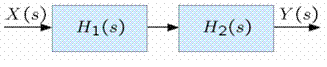
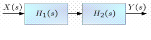
Systems are interconnections of sub-systems. For example, consider the cascade of LTI systems shown below.
The presumption in such a cascade is that H1(s) and H2(s) do not change when the two systems are connected.
1/ Cascade of a lowpass and a highpass filter
Suppose
and
have the following form.
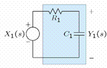
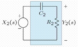
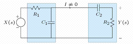
2/ Loading
Now cascade
and
.
l
Note that
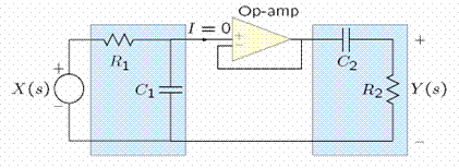
3/ Isolation
With the use of an op-amp, the two systems can be isolated from each other or buffered so that the system function is the product of the individual system functions.
Note that
4/ Conclusion
When we draw block diagrams of the form
we assume that the individual systems are buffered or that the loading of system 1 by system 2 is taken into account in
II. FEEDBACK EXAMPLES
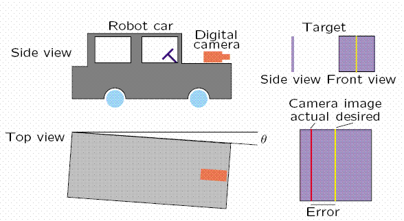
1/ Man-made system — robot car
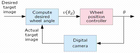
2/ Robot car block diagram
To drive the robot car to the target we use the camera to compare the measured target position with the desired target position. The difference is an error signal whose value is used to change the wheel position. Therefore, the output variable, the angle of the wheels, is fed back to the input to control the new output variable.
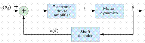
3/ Wheel position controller block diagram
The wheel controller system is itself a feedback system. A voltage proportional to the angular position of the motor shaft is subtracted from the desired value and the difference signal is used to drive the motor.
4/ Physiological control systems examples
Voluntary everyday activities
Driving a car
Filling a glass with water
Involuntary everyday occurrences
Pupil reflex
Blood glucose control
Spinal reflex
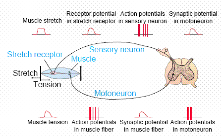
5/ Spinal reflex
Tapping the patella stretches muscle receptors that, through a neural feedback system, results in muscle contraction. This reflex is used in the maintenance of posture.
the study of living organisms and their interactions with one another and their environment.
Wine
discuss the biological phenomenon and provide pieces of evidence to show that it was responsible for the formation of eukaryotic organelles in an essay form
advantage of electronic microscope is easily and clearly while disadvantage is dangerous because its electronic. advantage of light microscope is savely and naturally by sun while disadvantage is not easily,means its not sharp and not clear
Abdullahi
cell theory state that every organisms composed of one or more cell,cell is the basic unit of life
Abdullahi
is like gone fail us
DENG
cells is the basic structure and functions of all living things
A scanning electron microscope (SEM) is ideal for situations requiring high-resolution imaging of surfaces. It is commonly used in materials science, biology, and geology to examine the topography and composition of samples at a nanoscale level. SEM is particularly useful for studying fine details,


 l
l