Published: January 30, 2007
By Richard G. Baldwin
Java Programming Notes # 2212
This is the first lesson in a two-part series designed to teach you how to write servlets to produce SVG code that will be rendered in graphic form by an SVG-compatible browser.
In this lesson, you will learn how write an SVG graphics library to eliminate or at least alleviate the requirement to write raw XML code or raw JAXP DOM code. This tutorial will introduce you to the beginnings of an SVG graphics library that makes it possible for you to produce SVG output simply by making Java method calls.
I recommend that you open another copy of this document in a separate browser window and use the following links to easily find and view the figures and listings while you are reading about them. You may also find it useful to open a third browser window at the Resources section near the end of the document. That will make it easy for you to open those resources when they are mentioned in the text.
I recommend that you also study the other lessons in my extensive collection of online Java tutorials. You will find a consolidated index at www.DickBaldwin.com.
|
When we write desktop applications using Java, we have access to Sun's Java 2D API (see Resources). We can easily use the API to provide rich graphical output for the benefit of the user.
Servlets
However, if we are writing servlets instead of desktop applications, it isn't obvious that the Java 2D API is directly useful. How can we provide the same level of rich graphical output that is possible with desktop applications?
I suppose that one possibility would be to cause the servlet to produce an output that causes the web client to download and execute an applet. Although I have never done so, it seems that an approach like that would make the Java 2D API available to the servlet/applet programmer.
|
Another possibility might be to cause the servlet to produce an output consisting of JavaScript code that makes use of Walter Zorn's JavaScript graphics library (see Resources). That might not be a bad idea, except that as of this writing, the capabilities of Zorn's graphics library fall far short of the capabilities of the Java 2D API.
On the other hand, since the code produced by the use of the library is simply JavaScript code, the output should be compatible with most, if not all browsers that are in common use as of the time of this writing. I will have more to say about the use of Zorn's library in a future tutorial on producing graphic output with the Google Web Toolkit (GWT).
|
Another approach is to use Scalable Vector Graphics (see Resources). Scalable Vector Graphics, (or SVG as it is more commonly known), is a W3C recommendation for the use of a special dialect of XML for the production of graphical output.
As the title of this tutorial suggests, the use of SVG with Java is the main topic of this tutorial. In this and Part 2 of this tutorial, I will teach you how to write servlets to produce SVG code that will be rendered in graphic form by an SVG-compatible browser.
The capabilities of SVG are extensive, and don't have to take a backseat to the Java 2D API.
|
There are some downsides to SVG. Unfortunately, not all browsers currently support SVG, and those that do don't necessarily support it fully.
Firefox 1.5 and later versions of Firefox support a subset of SVG.
IE 6 doesn't support SVG directly, but there is a plug-in available from Adobe (see Resources) that reportedly makes it possible to render SVG in IE 6. (Since I don't make much use of IE, I have never installed the SVG plug-in.)
Requires XML code
Another downside to the use of SVG for many programmers is the requirement to produce XML code in a special dialect that describes the graphic image. One way to accomplish this is to simply code the raw XML code into output statements so that it will be written into the output. This is difficult even for persons with considerable expertise in XML, SVG, and Java programming if for no reason other than the requirement to use escape sequences for numerous quotation marks that are required in the raw XML code.
A somewhat easier way, but one that is still not ideal, is to write JAXP DOM code to describe the desired graphics image in a DOM tree, and then to use JAXP to transform the DOM tree into the required raw XML code. Using JAXP DOM code to produce a DOM tree that represents a complex graphic can be a laborious task.
One of the purposes of this tutorial is to show you how you can write your own SVG graphics library to eliminate (or at least alleviate) the requirement to write raw XML code or raw JAXP DOM code. This tutorial will introduce you to the beginnings of an SVG graphics library that makes it possible to produce SVG output code simply by making typical Java method calls.
Breakdown between parts of the tutorial
I will present and explain two sample programs in this lesson followed by two additional sample programs in part 2.
The first sample program that I will explain in this lesson will:
The graphic image can be rendered by manually loading the SVG file into Firefox 1.5.
Lots of tedious programming is required
As you will see, even for a simple graphics image, this program requires the programmer to write many statements consisting of raw JAXP DOM code, which is later transformed into raw XML code. That is definitely not a fun way to spend your summer vacation.
An SVG graphics library
The second sample program that I will explain in this lesson moves most of the difficult and tedious code into a small SVG graphics library class. This makes it possible for the application programmer to concentrate on the use of the methods in the graphics library rather than having to concentrate on the nitty-gritty details of SVG and JAXP DOM code.
The SVG graphics library that I will present and explain is far from complete. However, it will serve as a proof of concept and will show you a methodology for writing your own SVG graphics library.
A requirement for XHTML files
While you can use Firefox 1.5 to render SVG code that is contained in an SVG file simply by manually loading the SVG file into the browser, as near as I can determine, in order to cause Firefox to render SVG code that is downloaded from a web site, the SVG code must be presented in the form of an XHTML file.
|
A useful capability
The capability demonstrated by the program described above will be useful for the creation of static XHTML files containing SVG graphics that you may want to post on your web site for downloading by your clients.
The program will also be useful as a precursor to creating inline SVG code in a servlet and to cause that SVG code to be rendered in a Firefox browser that accesses the servlet. That will be the purpose of a servlet program that I will also present and explain in part 2 of this tutorial.
What about internal references to SVG files?
A third option is to create an SVG file stored on a web server and then to reference that file for downloading from within an XHTML file. Presumably, the SVG file could be a static file, or could be a temporary file that is created dynamically by a servlet immediately before the XHTML code is sent from the servlet to the client.
So far, I have been unable to get this to work, but my problems seem to have more to do with server administration issues than with Java code, SVG code, or XML code. Maybe I will get those issues resolved and can show you how to do that in part 3 of this tutorial, (which is not currently on my list of things to do).
The basic image
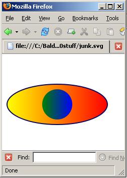
Figure 1 shows the basic image that I will be working with in this tutorial.
Figure 1. The basic image.
|
|
This image consists of an ellipse with a blue border. The thickness of the border is two pixels. A circle without a border is placed inside the ellipse.
The fill color for the ellipse is a color gradient that goes from yellow on the left to red on the right. The fill color for the circle is a color gradient that goes from green on the left to blue on the right. In both cases, the starting and ending points for the gradient are at the left and right edges of the graphic object being filled.
Horizontally compressed color gradient
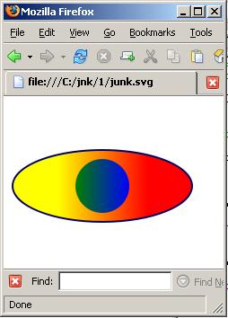
Figure 2 shows a somewhat different take on the same basic image.
Figure 2. Image with horizontally compressed gradient.
|
|
Figure 2 shows the same image as Figure 1, except that in Figure 2, the gradient begins twenty-five percent of the way across the ellipse going from left to right and ends seventy-five percent of the way across. Thus, the left one-fourth of the ellipse is solid yellow and the right one-fourth is solid red. The color gradient progresses from yellow to red between these two points.
Won't use this image
Other than to show you that this is possible using SVG color gradients, I won't be using the version of the image shown in Figure 2 in this tutorial. However, at an appropriate point, I will explain the code changes that were required to produce the image shown in Figure 2.
When I get into the use of XHTML files in part 2 of this tutorial, I will also add a containing box and some text to the image shown in Figure 1.
Why bother?
At this point, you may be wondering why anyone would bother with SVG image files when they could be using more conventional bitmap image files such as JPEG files and GIF files. There are at least two good reasons why it may be attractive to use SVG in place of bitmaps:
Scalability
Once an image has been committed to a bitmapped image format such as GIF or JPEG, the ability to scale the image to make it larger is greatly impaired. In particular, if you were to attempt to enlarge the typical bitmapped icons that you see on your computer's desktop, you would see that they become very grainy when enlarged. While it may be possible to do some sort of interpolation to decrease the graininess, bitmapped images were never intended to be enlarged and attempts to enlarge bitmapped images always seem to be marginal at best.
On the other hand, SVG files are designed to be displayed at any scale with little or no loss of quality. Hence the name Scalable Vector Graphics.
Bandwidth
As an experiment, I cropped the JPEG image shown in Figure 1 down to the smallest rectangle that would contain the ellipse. The result is shown in Figure 3. (As you can see, I actually cropped it a little too much and clipped off part of the border at the top.)
Figure 3. A cropped version of Figure 1.

|
After cropping and saving the image, (despite the fact that JPEG uses a lossy compression algorithm that degrades the quality of the image), the size of the JPEG file shown in Figure 3 was still 3,534 bytes. The SVG file required to produce the image, on the other hand, was only 604 bytes. Therefore, for this example, the bandwidth required to download or otherwise transmit the JPEG image file was more than six times greater than the bandwidth required to download the SVG file. Add this to the fact that lossy JPEG compression degrades the quality of the image and bandwidth considerations also stand out as a good reason to use SVG coding instead of bitmapped images.
Java 2D API versus SVG
Programming to produce images using the Java 2D API is completely different from programming to produce images using the SVG. There are major differences in at least the following categories:
Java 2D API specifications
The "Java 2D API Specification" (see Resources) and its associated documentation constitutes a "How To" manual for writing programs that will produce certain graphic images on the computer screen when a Java program has been compiled and executed. For example, the documentation for the Ellipse2D class tells you everything that you need to know to instantiate and configure an object of the Ellipse2D class. The assumption is that you will instantiate and configure such as object as part of a larger overall program. Then when you compile and execute the program using the Java virtual machine, a visual rendering of the ellipse will appear on the screen.
|
On the other hand, the "Scalable Vector Graphics (SVG) 1.1 Specification" (see Resources) is not a "How To" manual. Rather, it is something of a "What to Produce" manual. In other words, it doesn't tell you how to do anything. Instead, it tells you what you must produce in the way of XML data if you want to be able to use that data to cause certain graphic images to be displayed by an SVG-capable rendering engine.
Few if any assumptions
The SVG specifications make no assumptions as to the program that will be used to render the XML code into visual graphic images. Also, they make no assumptions regarding the display medium on which those images will be rendered. The display medium could be paper, it could be a computer screen or a PDA screen, or probably could even be a hologram.
|
Furthermore, the SVG specifications don't tell you how to write the program that will be used to produce the required SVG/XML output. In fact, the specifications make no assumptions as to what programming environment will be used to write a program that can produce the required SVG/XML output.
What about the SVG rendering engine?
The SVG specifications provide no instructions regarding the use of a particular programming environment to write a program that will render the SVG/XML code into visual graphic images. Rather, the specifications assume that you can figure out on your own how to write the code to produce the required SVG/XML output, and that you have access to a program that can reliably render that code on your desired display medium.
The bottom line regarding SVG
The bottom line is that the SVG specifications simply tell you what must be contained in the SVG/XML data in order to cause an SVG-capable rendering engine to produce the expected graphic images on the required display medium.
File format
Now let's consider the differences in the file formats required to produce images for the two approaches.
Java files
If you write and compile a Java program that uses the Java 2D API to produce graphic output, the instructions for producing that output are integrated into the bytecode file(s) that are used by the virtual machine to control the overall behavior of the program. That behavior causes your images to be rendered on the computer screen (or possibly on a printer, a PDA screen, a cell phone, etc.). Some of those bytecode files are produced by compiling the source code for your program. Other bytecode files are contained in the Java class libraries, having been placed there by the folks at Sun.
No single data file
The important point is that there is not a single identifiable data file that represents the image. Information representing the image is integrated into a lot of other information that determines the overall behavior of the program. There are probably very few people in the world that can examine the data in those files and make any sense out of it with regard to the graphic images that it will produce.
SVG files
SVG data files on the other hand are totally transparent. They are simply XML files, written in plain text according to the SVG specifications. They constitute a specific dialect of XML.
|
Thus, the contents of an SVG file consist primarily of the instructions necessary to tell a rendering engine how to draw the image. In fact, someone who understands the particular SVG dialect of XML could use a text editor to modify the SVG/XML data to cause the rendering engine to produce a totally different image from the one originally described by the SVG/XML data.
As mentioned earlier, I will present and explain two sample programs in this lesson followed by two additional sample programs part 2 of this series.
|
The first sample program named Svg01 will create a DOM tree describing the graphic image shown in Figure 1 in SVG format. Then it will transform the DOM tree into raw XML code and write the raw XML code into an XML file (otherwise known as an SVG file) named junk.svg. The graphic image can be rendered by manually loading the SVG file into Firefox 1.5.
As you will see, this first program requires quite a bit of difficult and tedious programming.
Svg02
The second sample program named Svg02 moves most of the difficult and tedious code into a small SVG graphics library of my own design. Having the graphics library available makes it possible for the application programmer to concentrate on the use of the methods in the library rather than having to concentrate on the nitty-gritty details of SVG, XML, or JAXP DOM coding.
|
Before getting into the programming details, I want to present and briefly explain the contents of the SVG/XML file produced by the program. A listing of that code begins in Listing 1.
However, even before getting into that, I want to highlight a few good online resources on the topic. (You will also find links to these resources in the Resources section so that you can easily find them later). These resources may be useful in helping you to interpret the SVG specifications.
The article titled Create vector graphics in the browser with SVG by Uche Ogbuji provides numerous examples showing graphic images along with the corresponding raw XML code.
The article titled SVG Tutorial is an excellent resource for understanding how the SVG specifications translate into XML code.
The article titled SVG Basics is another good resource for helping you to associate raw XML code with the graphic images that are produced by a rendering engine on the basis of that code.
Abbreviated SVG/XML code for Figure 1
Now, getting back on topic, Listing 1 shows an abbreviated version of the raw XML code that was rendered in Firefox 1.5 to produce Figure 1. Much of the raw XML code was omitted from Listing 1 to make it easier to see the overall structure of the document.
Listing 1. Abbreviated SVG/XML code for Figure 1.
<?xml version="1.0" encoding="UTF-8" standalone="no"?>

<svg height="100%" version="1.1" width="100%"
  xmlns="http://www.w3.org/2000/svg">

  <defs>
    ...
  </defs>

  <g>
    ...
  </g>

</svg>
|
The XML declaration
The first line in Listing 1 is an XML declaration. Since this is not intended to be an XML tutorial, I won't attempt to explain its purpose. Suffice it to say that it probably needs to be there. I'm sure that if you want to learn more about it, you can use Google to find more material on the topic than you can possibly find the time to read.
The root element
Every XML document requires a root element, which contains all of the other elements. In this case, the root element is the element named svg shown in Listing 1.
The purpose of the version attribute shown in Listing 1 is probably fairly obvious. The same is true of the height and width attributes, although the meaning of their values may not be clear. My recommendation is that you simply experiment with the values for the height and width attributes and you will probably be able to determine for yourself the behavior that they induce.
The remaining element attribute for the svg element shown in Listing 1 is known as a namespace attribute. The purpose of a namespace attribute is far too complicated for me to try to explain in this lesson. If you are really interested in its purpose, I'm confident that you will find a large amount of explanatory information on the web. Otherwise, just accept the fact that it needs to be there.
The defs element
The defs element shown in Listing 1 is simply a container for two elements that I will explain later. These two elements provide definitions of the two different color gradients that you see in Figure 1. One color gradient goes from yellow to red and the other color gradient goes from green to blue. Each gradient definition is given a name, which can be referred to later to cause other graphic objects to be filled using those color gradients.
The g element
Listing 1 also shows an element named g, which serves as a container for the ellipse element and the circle element shown in Figure 1.
Parent-child relationships
In XML terminology, the defs element and the g element are both child elements of the svg element. From a DOM tree perspective, they are both child nodes of the node in the tree that represents the svg element. This will be important to understand later when we get into the Java/JAXP DOM tree code that I used to represent the image.
Abbreviated defs element
Listing 2 shows an abbreviated version of the defs element with some of the content of the element deleted for clarity.
Listing 2. Abbreviated defs element.
<defs>
  <linearGradient id="gradientA">
    ...
  </linearGradient>

  <linearGradient id="gradientB">
    ...
  </linearGradient>
</defs>
|
As you can see from Listing 2, the defs element has two child elements, both of which are linearGradient elements. At this point we are getting a little closer to something that describes what you see in Figure 1.
Identification attributes for linear gradient elements
The first linearGradient element has an attribute named id with a value of gradientA. As you will see later, the definition of the ellipse element refers to this id value to cause the ellipse shown in Figure 1 to be filled with the color gradient that is defined in the first linearGradient element.
Similarly, the second linearGradient element shown in Listing 2 has an id attribute value of gradientB. You will see later that the circle element refers to this id value to cause the circle shown in Figure 1 to be filled with the color gradient that is defined in the second linearGradient element.
One complete linearGradient element
Listing 3 shows the complete linearGradient element for the first linearGradient element in Listing 2.
Listing 3. One complete linearGradient element.
<linearGradient id="gradientA"> <stop offset="0%" style="stop-color:yellow;"/> <stop offset="100%" style="stop-color:red;"/> </linearGradient> |
|
As you can see, the linearGradient element shown in Listing 3 has two child elements, each of which is a stop element.
The offset attribute
The offset attribute of the first stop element defines the point on the left side of the image at which the color begins to change. This point is defined as a percentage of the total width of the component being filled with a gradient color. As you can see, I used a value of 0%, specifying that the color should begin changing immediately at the left edge of the ellipse.
The style attribute
The value of the style attribute in the first stop element defines the beginning color at the left. As you can see, I set this to yellow causing the left edge of the ellipse in Figure 1 to be yellow.
Attributes of the second stop element
The value of the offset attribute in the second stop element in Listing 3 defines the point at which the color finishes changing. I set this to 100% causing the color to change all the way to the right edge of the ellipse in Figure 1.
The value of the style attribute in the second stop element defines the ending color. I set this to red causing the right edge of the ellipse in Figure 1 to be red.
As a result of this definition for a linear gradient, the ellipse, which is filled with color according to this definition, makes a smooth transition from yellow on the left to red on the right in Figure 1.
Another complete linearGradient element
Listing 4 shows the complete version of the second linearGradient element from Listing 2.Listing 4. Another complete linearGradient element.
<linearGradient id="gradientB"> <stop offset="0%" style="stop-color:green;"/> <stop offset="100%" style="stop-color:blue;"/> </linearGradient> |
The circle in Figure 1 was filled using the definition of gradientB shown in Listing 4. By now, you should be able to interpret the material in Listing 4 and understand how that definition causes the color of the circle in Figure 1 to transition smoothly from green on the left to blue on the right.
The ellipse and circle elements
Listing 5 shows the complete contents of the element named g from Listing 1.
Listing 5. The ellipse and circle elements.
<g>
  <ellipse cx="110" cy="100" rx="100" ry="40"
    style="fill:url(#gradientA);
           stroke:rgb(0,0,100);
           stroke-width:2"/>

  <circle cx="110" cy="100" r="30"
    style="fill:url(#gradientB)"/>
</g>
|
As you can see, the element named g has two child elements. One is an ellipse element and the other is a circle element.
The circle element
I will begin the discussion with the circle element because it is the simpler of the two. The appearance of the circle is determined by the values of the four attributes shown in Listing 5. For example, the values of the attributes named cx and cy define the location coordinates of the center of the circle, given in pixels relative to the upper-left corner of the white area in Figure 1.
The value of the attribute named r defines the radius of the circle.
The value of the style attribute for the circle in Listing 5 specifies that the circle is to be filled according to the definition of the linearGradient with an id of gradientB shown in Listing 4.
The ellipse element
The ellipse element in Listing 5 is a little more complicated than the circle element. To begin with, because it is not round, more information is required to define its shape. The values of the attributes named cx and cy have the same meaning as for the circle. However, the ellipse doesn't have a single radius attribute. Rather, the value of the attribute named rx defines the distance from the center to either the left or right end of the ellipse. Similarly, the value of the attribute named ry defines the distance from the center to either the top or the bottom of the ellipse.
The style attribute of the ellipse element
The style attribute is also more complicated. The style element is subdivided into three parameters with the following names:
Each parameter name is separated from its value by a colon. The three parameters are separated from each other by semicolons.
The fill parameter
The fill parameter has the same meaning as for the circle. In other words, the fill parameter specifies that the ellipse is to be filled according to the definition of the linearGradient with an id value of gradientA in Listing 4.
Style parameters that define the border on the ellipse
The other two style parameters define the visual characteristics of the border on the ellipse as shown in Figure 1.
|
The stroke-width parameter specifies the thickness of the border. In this case, I caused the border to have a thickness of two pixels.
Putting it all together
Putting all the pieces together, Listing 6 shows the complete contents of the SVG file used to render the image in Figure 1.
Listing 6. The complete contents of the SVG/XML file.
<?xml version="1.0" encoding="UTF-8" standalone="no"?>
<svg height="100%" version="1.1" width="100%"
  xmlns="http://www.w3.org/2000/svg">

<defs>
<linearGradient id="gradientA">
<stop offset="0%" style="stop-color:yellow;"/>
<stop offset="100%" style="stop-color:red;"/>
</linearGradient>

<linearGradient id="gradientB">
<stop offset="0%" style="stop-color:green;"/>
<stop offset="100%" style="stop-color:blue;"/>
</linearGradient>
</defs>

<g>
<ellipse cx="110" cy="100" rx="100" ry="40"
  style="fill:url(#gradientA);
         stroke:rgb(0,0,100);
         stroke-width:2"/>

<circle cx="110" cy="100" r="30"
  style="fill:url(#gradientB)"/>
</g>

</svg>
|
A plain text file
As you can see, an SVG file is a plain text file, which you could produce with a text editor if you had a reason to do so. Also, if you knew what you were doing, you could use a text editor to modify the file and thus cause the modified file to render into a different image.
Just a bunch of characters
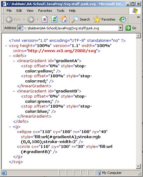
Unlike a JPEG or GIF bitmapped file, the contents of the SVG file shown in Listing 6 do not constitute an image. Rather, those contents simply provide the instructions by which an SVG-capable rendering engine (such as Firefox 1.5) can produce an image. Without the rendering engine, the contents of the SVG file are worthless. For example, if you were to load the SVG file shown in Listing 6 into IE 6 without first installing the SVG plug-in, all you would see would be a very nice indented and color-coded listing of the XML text shown in Listing 6. You would not see the image shown in Figure 1, which was produced by loading the SVG file into Firefox 1.5.
Loading the SVG file into IE 6
In fact, Figure 4 shows the result of loading the SVG/XML file into an IE 6 browser for which the SVG plug-in hasn't been installed. Contrast the image in Figure 4 with the image in Figure 1, and you will understand what I mean by the importance of an SVG rendering engine.
Figure 4. Viewing the SVG/XML file in IE 6.
|
|
Now that you know all about the SVG/XML output produced by the program named Svg01, it's time to take a look at the program in order to understand how it produces that output.
Program description for Svg01
The purpose of this program is to create a DOM tree describing a specific graphic image in SVG format, to transform it into raw XML code, and to write that raw XML code out into an XML file named junk.svg.
Along the way, the DOM is displayed in XML format on the command-line screen. Note, however that the output on the command-line screen is all on a single line with no line breaks or indentation. Therefore, it is useful only for test and debug purposes.
Portions of this program were based on the earlier program named Xslt01, which I explained in lesson number 2202 titled "Getting Started with Java JAXP and XSL Transformations (XSLT)" (see Resources).
The output file produced by this program can be rendered by loading it into Firefox 1.5. The program was tested using J2SE 5.0, Firefox 1.5.0.8, and WinXP.
I will explain this program in fragments. A complete listing of the program is provided in Listing 26 near the end of the lesson.
Beginning of the class for Svg01
Listing 7 shows the beginning of the class named Svg01.
Listing 7. Beginning of the class for Svg01.
public class Svg01 {

  public static void main(String[] args){
    try{
      DocumentBuilderFactory factory =
                     DocumentBuilderFactory.newInstance();

      DocumentBuilder builder =
                             factory.newDocumentBuilder();
      Document document = builder.newDocument();
      document.setXmlStandalone(false);
|
Create a DOM tree
The purpose of the code in Listing 7 is to begin the process of creating a DOM tree that represents the XML code that will be used to render the image shown in Figure 1. The code in Listing 7 was explained in my earlier lesson number 2200 titled "Java API for XML Processing (JAXP), Getting Started" (see Resources). Therefore, I won't bore you by repeating that explanation here. You should refer to the explanation in the earlier lesson if you don't understand the code in Listing 7.
Note that the code in Listing 7 ends up having created an object of the type Document, and having saved a reference to that object in a reference variable named document. The Document object represents the entire XML document. Conceptually, it is the root of the document tree, and provides the primary access to the document's data.
Create root node named svg
Listing 8 creates the root node named svg and appends it to the document node. Thus, svg is a child node of document.
Listing 8. Create root node named svg.
      Element svg =
                   (Element)document.createElement("svg");
      document.appendChild(svg);

      //Set some attributes on the root node that are
      // required for proper rendering.
      svg.setAttribute("width","100%");
      svg.setAttribute("height","100%");
      svg.setAttribute("version","1.1");
      svg.setAttribute(
                    "xmlns","http://www.w3.org/2000/svg");
|
The node named svg in Listing 8 corresponds directly to the element named svg shown in Listing 1. Later on, when the DOM tree is transformed to raw XML code, this node will cause the svg element to be contained in the output SVG/XML code.
Set node attribute values on the svg node
In addition to creating the svg node, the code in Listing 8 also sets some attribute values on the node that are required for proper rendering later. These attribute values correspond directly to the element attributes shown in Listing 1.
Create the defs node
Listing 9 creates a node named defs that will eventually contain nodes that define two different color gradient schemes. The defs node corresponds directly to the element named defs shown in Listing 1, and is appended onto the svg node. Therefore, defs is a child node of the node named svg.
Listing 9. Create the defs node.
      Element defs =
                  (Element)document.createElement("defs");
      svg.appendChild(defs);
|
As you saw in Listing 2, a pair of linearGradient nodes will be created as child nodes of the defs node. The two linearGradient nodes will be identified as gradientA and gradientB. They will be referred to later to specify the fill colors for an ellipse node and a circle node.
Create a linearGradient node
Listing 10 creates the first of two linearGradient nodes (corresponding to the linearGradient elements shown in Listing 2), and appends the node to the defs node.
Listing 10. Create a linearGradient node.
      Element linearGradientA =
        (Element)document.createElement("linearGradient");
      defs.appendChild(linearGradientA);

      linearGradientA.setAttribute("id","gradientA");
|
As explained earlier, this node is given an attribute node named id with a value of gradientA.
Create the first stop node
Listing 11 creates a stop node corresponding to the first stop element shown in Listing 3. This stop node is appended to the linearGradient node, thus becoming a child node of the linearGradient node.
Listing 11. Create the first stop node.
      Element stopA =
                  (Element)document.createElement("stop");
      stopA.setAttribute("offset","0%");
      stopA.setAttribute("style","stop-color:yellow;");

      linearGradientA.appendChild(stopA);
|
Listing 11 also sets two attribute values that belong to the stop node. As you can see, the attribute values match the element attribute values for the first stop element shown in Listing 3.
This stop node, along with the stop node shown in Listing 12 causes the linearGradient node to provide a linear color gradient making a smooth transition from yellow to red, going from left to right as shown in Figure 1.
Create the second stop node
Listing 12 creates a stop node corresponding to the second stop element shown in Listing 3, and appends the stop node to the linearGradient node.
Listing 12. Create the second stop node.
      Element stopB =
                  (Element)document.createElement("stop");
      stopB.setAttribute("offset","100%");
      stopB.setAttribute("style","stop-color:red;");

      linearGradientA.appendChild(stopB);
|
Create and populate the other linearGradient node
In similar fashion, the code in Listing 13 creates a linearGradient node corresponding to the linearGradient element shown in Listing 4. The linearGradient node is given two stop nodes as child nodes, corresponding to the two stop elements shown in Listing 4.
Listing 13. Create and populate the other linearGradient node.
      //Now define linearGradientB, which provides a
      // linear color gradient from green to blue going
      // from left to right. Append it to the defs node.
      Element linearGradientB =
        (Element)document.createElement("linearGradient");
      defs.appendChild(linearGradientB);
      linearGradientB.setAttribute("id","gradientB");

      Element stopC =
                  (Element)document.createElement("stop");
      stopC.setAttribute("offset","0%");
      stopC.setAttribute("style","stop-color:green;");
      linearGradientB.appendChild(stopC);

      Element stopD =
                  (Element)document.createElement("stop");
      stopD.setAttribute("offset","100%");
      stopD.setAttribute("style","stop-color:blue;");
      linearGradientB.appendChild(stopD);
|
Create the ellipse and circle nodes
Listing 14 creates a g node and makes it a child of the svg node. This g node corresponds to the g element shown in Listing 5.
Also corresponding to Listing 5, the code in Listing 14 creates an ellipse node and a circle node and makes them child nodes of the g node. These two nodes correspond to the ellipse and circle elements shown in Listing 5.
Listing 14. Create the g node, the ellipse node, and the circle node.
      //Create a node named g that contains an ellipse
      // and a circle.  Append it to the svg node.
      Element gNode =
                     (Element)document.createElement("g");
      svg.appendChild(gNode);

      //Now create an ellipse with a blue border having
      // a thickness of two pixels. Color the ellipse in
      // the yellow-red style defined by linearGradientA.
      // Append the ellipse node to the g node.
      Element ellipseA  =
               (Element)document.createElement("ellipse");
      gNode.appendChild(ellipseA);
      ellipseA.setAttribute("cx","110");
      ellipseA.setAttribute("cy","100");
      ellipseA.setAttribute("rx","100");
      ellipseA.setAttribute("ry","40");
      ellipseA.setAttribute("style",
                            "fill:url(#gradientA);"
                            + "stroke:rgb(0,0,100);"
                            + "stroke-width:2");

      //Now place a circle at a location that will make
      // it appear that the circle is physically inside
      // the ellipse.  Note however that the circle is
      // not a child node of the ellipse.  They simply
      // occupy the same space in the display.  Color the
      // circle with the green-blue style defined by
      // linearGradientB. Append the circle node to the
      // g node.
      Element circleA  =
                (Element)document.createElement("circle");
      gNode.appendChild(circleA);
      circleA.setAttribute("cx","110");
      circleA.setAttribute("cy","100");
      circleA.setAttribute("r","30");
      circleA.setAttribute("style",
                            "fill:url(#gradientB)");
|
By now, the usage of the Java code to create the DOM tree should be sufficiently familiar to you that no explanation beyond the embedded comments in Listing 14 should be required.
The DOM tree is complete
At this point, the construction of the DOM tree representing the XML code required to produce the image shown in Figure 1 has been completed. If you are new to this process, you may be wondering what the advantage of a DOM tree is, since more Java code is required to construct it that is reflected in the XML code that it will be used to produce.
Basically, a DOM tree is a generalized way to represent an XML document. Once you have the tree, you can write code to perform a variety of modifications on the tree, such as moving child nodes among parents, etc. You can also transform the DOM tree into a variety of different output formats, including raw XML, HTML, PDF, etc. In this case, we will simply transform the DOM tree into a raw XML output file to be rendered by the SVG rendering engine in Firefox 1.5. (For test and debug purposes, we will also transform the DOM tree into a screen output showing the raw XML.)
The remaining program code
The remaining program code is shown in Listing 15. Most of the remaining code is used to transform the DOM tree into the raw XML screen display and raw XML output file described above.
Listing 15. The remaining program code.
      //Get a TransformerFactory object.
      TransformerFactory xformFactory =
                         TransformerFactory.newInstance();

      //Get an XSL Transformer object.
      Transformer transformer =
                            xformFactory.newTransformer();

      //This statement is new to this lesson.  It sets
      // the standalone property in the XML declaration,
      // which appears as the first line of the output
      // file.
      transformer.setOutputProperty(
                              OutputKeys.STANDALONE,"no");

      //Get a DOMSource object that represents the
      // Document object
      DOMSource source = new DOMSource(document);

      //Get a StreamResult object that points to the
      // screen. Then transform the DOM sending XML to
      // the screen.
      StreamResult scrResult =
                             new StreamResult(System.out);
      transformer.transform(source, scrResult);

      //Get an output stream for the output file.
      PrintWriter outStream = new PrintWriter("junk.svg");

      //Get a StreamResult object that points to the
      // output file.  Then transform the DOM sending XML
      // to the file
      StreamResult fileResult =
                              new StreamResult(outStream);
      transformer.transform(source,fileResult);
    }//end try block

    catch(Exception e){
      e.printStackTrace(System.err);
    }//end catch

  }// end main()
  //----------------------------------------------------//

}// class Svg01
|
Explained in an earlier lesson
Almost all of the code in Listing 15 was explained in my earlier lesson titled "Getting Started with Java JAXP and XSL Transformations (XSLT)" (see Resources) in conjunction with the program named Xslt01. Therefore, I won't bore you with another explanation of the same code.
The end of the program
Listing 15 also signals the end of the main method and the end of the class named Svg01. When the program terminates, it will have produced an output file in the current directory named junk.svg. You can load that file into your Firefox 1.5 browser, and you should see a graphic output that matches the image in Figure 1.
Or, you should be able to load the file into any other SVG rendering engine, such as IE 6 with the SVG plug-in installed, and you should see a graphic output that matches the image shown in Figure 1.
A lot of programming was required
By now you have probably realized that a lot of programming was required to write the program named Svg01, simply to produce the small XML file shown in Listing 6. You may have concluded that there must be an easier way. Although it requires more up-front programming effort, there is an easier way.
An easier way
If you will be doing very much of this type of programming, one easier way is to create a reusable SVG graphics library that will alleviate most of the tedious programming effort required to produce the SVG files that represent your images. I will use the program named Svg02 to illustrate the beginnings of just such an SVG graphics library of my own design. The major elements in the graphics library correspond to the major graphic elements in the SVG specification.
I also want to point out that most of the code shown in Listing 7 and Listing 15 is completely reusable from one graphic image to the next. Therefore, I also moved most of that code to methods in the library. These methods can be used over and over again with no requirement to rewrite the code each time the SVG code for a new graphic image is required.
Much more work will be required
Quite a lot of effort will be required to finish the graphic library and to bring it into full compliance with the SVG specifications. However, once the library is available it can be used to greatly reduce the amount of programming effort required to produce a new graphic image. For example, as you will see later, exclusive of the code in the new graphics library, the program named Svg02 produces the same SVG/XML output file as the program named Svg01 with only the following nine method calls:
Of the nine methods, only seven are required for the purpose of creating nodes that describe the graphic image. The remaining two are required to do some required setup and to write the output file.
Description of the program
This program is an update of the program named Svg01. The purpose of this update is to move most of the difficult and tedious code into a small SVG graphics library class named SvgGraphics so that the application programmer can concentrate on the characteristics of the required graphic images rather than having to concentrate on the details of SVG and JAXP/DOM programming.
Also, for convenience, the library contains two methods that are used to execute code that is the same regardless of the graphic image being produced.
The library is not complete
As mentioned earlier, the SVG graphics library is far from complete. In its current state, the library provides methods to produce the following types of DOM tree nodes:
Although a great deal more programming effort would be required to write a complete SVG graphics library, this program demonstrates proof of concept. The program illustrates an approach that could be used to create a graphics library that supports most of the features of the SVG specification.
Create and transform a DOM tree
This program creates a DOM tree describing the graphic image shown in Figure 1 in SVG format. Then it transforms the DOM tree into raw XML code and writes that code into an output XML file named junk.svg. Along the way, the DOM is displayed in raw XML format on the command-line screen.
The output file produced by this program can be rendered by loading it into Firefox 1.5.
The program was tested using J2SE 5.0, Firefox v1.5.0.8, and WinXP.
Will discuss in fragments
As is my custom, I will explain this program by discussing it in fragments. A complete listing of the program is provided in Listing 27 near the end of the lesson.
As before, the program begins by creating a DOM tree that represents the XML code that can be rendered to produce the image shown in Figure 1. The program and the main method begin in Listing 16.
Listing 16. Beginning of the Svg02 class.
public class Svg02{

  public static void main(String[] args){
    //Get the Document object.
    Document document = SvgGraphics.getDocument();
|
Listing 16 calls a convenience method in the graphics library to get a reference to an object of type Document. (You can view all of the methods in the graphics library in Listing 27.) The code in the method is essentially the same as that used in the previous program. If you understood the code in Listing 7, you should have no difficulty understanding the code in this new method. Therefore, this code shouldn't require further explanation.
Create the root node named svg
Listing 17 calls the graphics library method named getRootNode to
Listing 17. Create the root node named svg.
    //Create the root node named svg and append it
    // to the document.
    Element svg = SvgGraphics.getRootNode(document,
                                          "100%",
                                          "100%",
                                          "absolute",
                                          "0",
                                          "0");
|
If you understood the code in Listing 8, you should have no difficulty understanding the code for the method named getRootNode. Therefore, I won't explain it further at this point in the lesson.
Create the node named defs
Listing 18 calls the graphics library method named simpleElement to create a node named defs. This node will be the parent for a pair of linear gradient definition nodes.
Listing 18. Create the node named defs.
    Element defs = SvgGraphics.simpleElement(
                                   document,svg,"defs");
|
The method named simpleElement is shown in its entirety in Listing 27. This method calls the createElement method to create an element node (having no attributes) of the type given by the third incoming parameter ("defs" in this case). Then it appends the new node to the node specified by the second parameter (svg in this case) and returns a reference to the new node.
Create the first linearGradient node
Listing 19 calls the graphics library method named makeLinearGradient to create a new linearGradient node, which will be identified as gradientA.
Listing 19. Create the first linearGradient node.
    Element linearGradientA =
               SvgGraphics.makeLinearGradient(
                 document,            //this document
                 defs,                 //parent
                 "gradientA",         //id
                 "0%",                //beginning point
                 "stop-color:yellow;",//beginning color
                 "100%",              //ending point
                 "stop-color:red;");  //ending color
|
This method call defines a linearGradient node that provides a linear color gradient that transitions from yellow to red going from left to right. The method call also establishes the beginning and ending points of the gradient along with the beginning and ending colors.
The method named makeLinearGradient is shown in its entirety in Listing 27. I'm sure that by now you are getting tired of me saying this, but I will say it at least one more time. If you understood the code in Listing 10, Listing 11, and Listing 12, you should have no difficulty understanding the code in the method named makeLinearGradient. Therefore, I won't explain it further.
Create the second linearGradient node
Listing 20 calls the makeLinearGradient method to create the second linearGradient node.
Listing 20. Create the second linearGradient node.
    Element linearGradientB =
                SvgGraphics.makeLinearGradient(
                  document,           //this document
                  defs,                //parent
                  "gradientB",        //id
                  "0%",               //beginning point
                  "stop-color:green;",//beginning color
                  "100%",             //ending point
                  "stop-color:blue;");//ending color
|
This method call corresponds to Listing 13 in the previous program, providing a linear gradient that transitions from green on the left to blue on the right.
Create the g node
Listing 21 makes another call to the simpleElement method to create the g node. This will be the parent node for an ellipse node and a circle node, and corresponds to the first two executable statements in Listing 14 from the previous program.
Listing 21. Create the g node.
    Element g = SvgGraphics.simpleElement(
                                        document,svg,"g");
|
Create the ellipse node
Listing 22 calls the graphics library method named svgEllipse to create an ellipse node that represents the ellipse shown in Figure 1.
Listing 22. Create the ellipse node.
    //Create an ellipse with a blue border that is two
    // pixels thick. Fill the ellipse with the
    // yellow-red  gradient defined by linearGradientA.

    //Begin by defining the style for the ellipse
    String ellipseStyle =
          "fill:url(#gradientA);" //Fill using gradientA
          + "stroke:rgb(0,0,100);"//Border and its color
          + "stroke-width:2";     //Border width

    SvgGraphics.svgEllipse(document,//This document
                           g,//Owner
                           110,//Center x-coordinate
                           100,//Center y-coordinate
                           100,//Width
                           40, //Height
                           ellipseStyle);
|
To make it somewhat easier to format the code to fit into this narrow publication format, the code in Listing 22 begins by defining a String that specifies the style for the ellipse. A reference to that string is passed as the seventh parameter to the svgEllipse method that creates the node and causes it to become a child node of the g node.
Create a circle node
Listing 23 calls the graphics library method named svgCircle to create a node that represents the circle in Figure 1, and appends the new node to the g node.
Listing 23. Create a circle node.
    //Place a circle in a location that will make it
    // appear to be inside the ellipse. Specify a
    // style that will fill it with the green-blue
    // gradient defined by linearGradientB.
    SvgGraphics.svgCircle(document,//This document
                          g,//Owner
                          110,//Center x-coordinate
                          100,//Center y-coordinate
                          30, //Radius
                          "fill:url(#gradientB)");
|
In this case, the string specifying the style was rather short, so I simply defined it as part of the parameter list in the method call.
Transform the DOM and write the output file
The DOM tree that represents the raw XML code required to produce the image shown in Figure 1 is now complete. Listing 24 invokes the library method named transformTheDom to transform the DOM tree into raw XML code, write that code onto the command-line screen, and write that code into the output file named junk.svg.
Listing 24. Transform the DOM and write the output file.
SvgGraphics.transformTheDom(document,"junk.svg"); }// end main() }// class Svg02 |
The code in the method named transformTheDom is essentially the same as the code in Listing 15 from the previous program. If you understood that code, you should have no difficulty understanding the code in the method named transformTheDom.
Listing 24 also signals the end of the main method and the end of the class named Svg02.
I encourage you to copy the code from Listing 26 and Listing 27 into your text editor, compile it, and execute it. Then view the resulting SVG files in Firefox 1.5, or some other suitable SVG rendering engine. Experiment with the code, making changes, and observing the results of your changes.
Above all, enjoy the process. Programming can be fun if you approach it with a positive attitude.
This lesson is part 1 of a two-part series designed to teach you how to write servlets to produce SVG code that will be rendered in graphic form by an SVG-compatible browser.
In this lesson, I showed you how to write Java code to produce the raw XML code necessary to produce images using an SVG rendering engine.
First I showed you how to do it the hard way. Then I introduced the beginnings of an SVG graphics library that can be used to eliminate (or at least alleviate) the requirement to write raw XML code or to write raw JAXP DOM code. The SVG graphics library makes it possible to produce SVG output files simply by making typical Java method calls.
Part 2 of the series will show you how to take what you have learned in this lesson and apply it to the generation of XHTML files containing in-line SVG/XML code. Then it will teach you how to apply that knowledge to the writing of servlets that produce XHTML output containing in-line SVG/XML code.
A future lesson will teach you how to write servlets that produce XHTML output containing references to external SVG files in addition to in-line SVG/XML code.
Listing 25. Output XML file produced by both programs.
<?xml version="1.0" encoding="UTF-8" standalone="no"?>
<svg height="100%" version="1.1" width="100%"
  xmlns="http://www.w3.org/2000/svg">

<defs>
<linearGradient id="gradientA">
<stop offset="0%" style="stop-color:yellow;"/>
<stop offset="100%" style="stop-color:red;"/>
</linearGradient>

<linearGradient id="gradientB">
<stop offset="0%" style="stop-color:green;"/>
<stop offset="100%" style="stop-color:blue;"/>
</linearGradient>
</defs>

<g>
<ellipse cx="110" cy="100" rx="100" ry="40"
  style="fill:url(#gradientA);
         stroke:rgb(0,0,100);
         stroke-width:2"/>

<circle cx="110" cy="100" r="30"
  style="fill:url(#gradientB)"/>
</g>

</svg>
|
Listing 26. Java code for program Svg01.
/*File Svg01.java
Copyright 2006 R.G.Baldwin

The purpose of this program is to create a DOM tree
describing a specific graphic image in SVG format and to
write it out into an XML file named junk.svg. Along the
way, the DOM is displayed in XML format on the
command-line screen. Note, however that the output on the
command-line screen is all on a single line with no line
breaks or indentation. Therefore, it is useful only for
test and debug purposes.

Portions of this program are based on the earlier program
named Xslt01.java, which was explained in lesson
number 2202 named "Getting Started with Java JAXP and
XSL Transformations (XSLT)".

The output file produced by this program can be rendered
by loading it into Firefox 1.5.

Tested using J2SE 5.0, Firefox 1.5.0.8, and WinXP.
*********************************************************/

import javax.xml.parsers.*;
import org.w3c.dom.*;
import javax.xml.transform.*;
import javax.xml.transform.dom.DOMSource;
import javax.xml.transform.stream.StreamResult;
import java.io.*;

public class Svg01 {

  public static void main(String[] args){
    try{
      //Begin by creating a DOM tree that represents
      // the XML code that will render to produce the
      // image of interest.
      DocumentBuilderFactory factory =
                     DocumentBuilderFactory.newInstance();

      DocumentBuilder builder =
                             factory.newDocumentBuilder();
      Document document = builder.newDocument();
      document.setXmlStandalone(false);

      //Create the root node named svg and append it to
      // the document.
      Element svg =
                   (Element)document.createElement("svg");
      document.appendChild(svg);

      //Set some attributes on the root node that are
      // required for proper rendering.
      svg.setAttribute("width","100%");
      svg.setAttribute("height","100%");
      svg.setAttribute("version","1.1");
      svg.setAttribute(
                    "xmlns","http://www.w3.org/2000/svg");

      //Create a node named defs that contains the
      // definitions of two different gradient coloring
      // schemes. The definitions are identified as
      // linearGradientA and linearGradientB.  They will
      // be referred to later to specify the fill colors
      // for an ellipse and a circle.
      Element defs =
                  (Element)document.createElement("defs");
      svg.appendChild(defs);

      //Now define linearGradientA, which provides a
      // linear gradient from yellow to red going from
      // left to right and append it to the defs node.
      Element linearGradientA =
        (Element)document.createElement("linearGradient");
      defs.appendChild(linearGradientA);
      linearGradientA.setAttribute("id","gradientA");

      Element stopA =
                  (Element)document.createElement("stop");
      stopA.setAttribute("offset","0%");
      stopA.setAttribute("style","stop-color:yellow;");
      linearGradientA.appendChild(stopA);

      Element stopB =
                  (Element)document.createElement("stop");
      stopB.setAttribute("offset","100%");
      stopB.setAttribute("style","stop-color:red;");
      linearGradientA.appendChild(stopB);

      //Now define linearGradientB, which provides a
      // linear color gradient from green to blue going
      // from left to right. Append it to the defs node.
      Element linearGradientB =
        (Element)document.createElement("linearGradient");
      defs.appendChild(linearGradientB);
      linearGradientB.setAttribute("id","gradientB");

      Element stopC =
                  (Element)document.createElement("stop");
      stopC.setAttribute("offset","0%");
      stopC.setAttribute("style","stop-color:green;");
      linearGradientB.appendChild(stopC);

      Element stopD =
                  (Element)document.createElement("stop");
      stopD.setAttribute("offset","100%");
      stopD.setAttribute("style","stop-color:blue;");
      linearGradientB.appendChild(stopD);

      //Create a node named g that contains an ellipse
      // and a circle.  Append it to the svg node.
      Element gNode =
                     (Element)document.createElement("g");
      svg.appendChild(gNode);

      //Now create an ellipse with a blue border having
      // a thickness of two pixels. Color the ellipse in
      // the yellow-red style defined by linearGradientA.
      // Append the ellipse node to the g node.
      Element ellipseA  =
               (Element)document.createElement("ellipse");
      gNode.appendChild(ellipseA);
      ellipseA.setAttribute("cx","110");
      ellipseA.setAttribute("cy","100");
      ellipseA.setAttribute("rx","100");
      ellipseA.setAttribute("ry","40");
      ellipseA.setAttribute("style",
                            "fill:url(#gradientA);"
                            + "stroke:rgb(0,0,100);"
                            + "stroke-width:2");

      //Now place a circle at a location that will make
      // it appear that the circle is physically inside
      // the ellipse.  Note however that the circle is
      // not a child node of the ellipse.  They simply
      // occupy the same space in the display.  Color the
      // circle with the green-blue style defined by
      // linearGradientB. Append the circle node to the
      // g node.
      Element circleA  =
                (Element)document.createElement("circle");
      gNode.appendChild(circleA);
      circleA.setAttribute("cx","110");
      circleA.setAttribute("cy","100");
      circleA.setAttribute("r","30");
      circleA.setAttribute("style",
                            "fill:url(#gradientB)");

      //Most of the remaining code transforms the DOM
      // tree into a screen display and an output file.
      // This code was explained in the earlier lesson
      // named "Getting Started with Java JAXP and XSL
      // Transformations (XSLT)" in conjunction with the
      // program named Xslt01.

      //Get a TransformerFactory object.
      TransformerFactory xformFactory =
                         TransformerFactory.newInstance();

      //Get an XSL Transformer object.
      Transformer transformer =
                            xformFactory.newTransformer();

      //This statement is new to this lesson.  It sets
      // the standalone property in the XML declaration,
      // which appears as the first line of the output
      // file.
      transformer.setOutputProperty(
                              OutputKeys.STANDALONE,"no");

      //Get a DOMSource object that represents the
      // Document object
      DOMSource source = new DOMSource(document);

      //Get a StreamResult object that points to the
      // screen. Then transform the DOM sending XML to
      // the screen.
      StreamResult scrResult =
                             new StreamResult(System.out);
      transformer.transform(source, scrResult);

      //Get an output stream for the output file.
      PrintWriter outStream = new PrintWriter("junk.svg");

      //Get a StreamResult object that points to the
      // output file.  Then transform the DOM sending XML
      // to the file
      StreamResult fileResult =
                              new StreamResult(outStream);
      transformer.transform(source,fileResult);
    }//end try block

    catch(Exception e){
      e.printStackTrace(System.err);
    }//end catch

  }// end main()
  //----------------------------------------------------//

}// class Svg01
|
Listing 27. Java code for program Svg02.
/*File Svg02.java
Copyright 2006 R.G.Baldwin

This program is an update of the program named Svg01.  The
purpose of this update is to move most of the difficult
and tedious code into a small SVG graphics library class
named SvgGraphics so that the application programmer can
concentrate on the use of the graphics library rather than
having to concentrate on the details of SVG.

For convenience, the library also contains a couple of
methods that are used to execute code that is the same
regardless of the graphic image being produced.

The SVG graphics library is far from complete.  In its
current state, the library provides methods to produce the
following DOM tree nodes.

  A simple element with no attributes.
  A linear gradient element.
  An ellipse
  A circle

Although a great deal more programming effort would be
required to write a complete SVG graphics library, this
program serves its intended purpose of provides a proof of
concept. The program illustrates an approach that could be
used to create a graphics library that supports most of
the features of the SVG specification.

The program creates a DOM tree describing a specific
graphic image in SVG format and writes it out into an XML
file named junk.svg. Along the way, the DOM is displayed
in raw XML format on the command-line screen. Note,
however that the output on the command-line screen is all
on a single line with no line breaks or indentation.
Therefore, it is useful only for test and debug purposes.

Portions of this program are based on the earlier program
named Xslt01.java, which was explained in lesson
number 2202 titled "Getting Started with Java JAXP and
XSL Transformations (XSLT)".

The output file produced by this program can be rendered
by loading it into Firefox 1.5.

Tested using J2SE 5.0, Firefox v1.5.0.8, and WinXP.
*********************************************************/

import javax.xml.parsers.*;
import org.w3c.dom.*;
import javax.xml.transform.*;
import javax.xml.transform.dom.DOMSource;
import javax.xml.transform.stream.StreamResult;
import java.io.*;

public class Svg02{

  public static void main(String[] args){

    //Begin by creating a DOM tree that represents
    // the XML code that will render to produce the
    // image of interest.

    //Get the Document object.
    Document document = SvgGraphics.getDocument();

    //Create the root node named svg and append it
    // to the document.
    Element svg = SvgGraphics.getRootNode(document,
                                          "100%",
                                          "100%",
                                          "absolute",
                                          "0",
                                          "0");

    //Create a node named defs, which will be the parent
    // for a pair of linear gradient definitions.
    Element defs = SvgGraphics.simpleElement(
                                   document,svg,"defs");

    //Define linearGradientA, which provides a linear
    // gradient from yellow to red going from left to
    // right. Establish the beginning and ending points
    // along with the beginning and ending colors in
    // the process
    Element linearGradientA =
               SvgGraphics.makeLinearGradient(
                 document,            //this document
                 defs,                 //parent
                 "gradientA",         //id
                 "0%",                //beginning point
                 "stop-color:yellow;",//beginning color
                 "100%",              //ending point
                 "stop-color:red;");  //ending color


    //Define linearGradientB, which provides a linear
    // gradient from green to blue going from left to
    // right.
    Element linearGradientB =
                SvgGraphics.makeLinearGradient(
                  document,           //this document
                  defs,                //parent
                  "gradientB",        //id
                  "0%",               //beginning point
                  "stop-color:green;",//beginning color
                  "100%",             //ending point
                  "stop-color:blue;");//ending color

    //Create a node named g, which will be the parent
    // for an ellipse and a circle.
    Element g = SvgGraphics.simpleElement(
                                   document,svg,"g");

    //Create an ellipse with a blue border that is two
    // pixels thick. Fill the ellipse with the
    // yellow-red  gradient defined by linearGradientA.
    //Begin by defining the style for the ellipse
    String ellipseStyle =
          "fill:url(#gradientA);" //Fill using gradientA
          + "stroke:rgb(0,0,100);"//Border and its color
          + "stroke-width:2";     //Border width
    SvgGraphics.svgEllipse(document,//This document
                           g,//Owner
                           110,//Center x-coordinate
                           100,//Center y-coordinate
                           100,//Width
                           40, //Height
                           ellipseStyle);

    //Place a circle in a location that will make it
    // appear to be inside the ellipse. Specify a
    // style that will fill it with the green-blue
    // gradient defined by linearGradientB.
    SvgGraphics.svgCircle(document,//This document
                          g,//Owner
                          110,//Center x-coordinate
                          100,//Center y-coordinate
                          30, //Radius
                          "fill:url(#gradientB)");

    //Transform the DOM and write the output.
    SvgGraphics.transformTheDom(document,"junk.svg");

  }// end main()
  //----------------------------------------------------//

}// class Svg02
//======================================================//

//This is a small proof-of-concept graphics class that
// provides method calls for the creation of the following
// DOM tree nodes:
//  A simple element with no attributes.
//  A linear gradient element.
//  An ellipse
//  A circle

//Each method receives a reference to the overall document
// along with a reference to the parent for the new node.
//When the method returns, the new node has been appended
// to the parent node.
class SvgGraphics{

  //This method returns a reference to a simple XML
  // element node that has no attributes.
  static Element simpleElement(Document document,
                               Element parent,
                               String type){
    Element theElement =
                    (Element)document.createElement(type);
    parent.appendChild(theElement);
    return theElement;
  }//end simpleElement
  //----------------------------------------------------//

  //This method returns a reference to a linear gradient
  // node for which the beginning and ending points and
  // the beginning and ending colors have been
  // established. The id value is the value by which the
  // gradient is referenced in order to apply it to
  // a component.
  static Element makeLinearGradient(Document document,
                                    Element parent,
                                    String id,
                                    String beginningPoint,
                                    String beginningColor,
                                    String endingPoint,
                                    String endingColor){
    Element linearGradient =
        (Element)document.createElement("linearGradient");
    parent.appendChild(linearGradient);
    linearGradient.setAttribute("id",id);

    //Establish the point at which the gradient begins
    // and the color at the beginning point.
    Element beginningElement  =
                  (Element)document.createElement("stop");
    beginningElement.setAttribute(
                                 "offset",beginningPoint);
    beginningElement.setAttribute("style",beginningColor);
    linearGradient.appendChild(beginningElement);

    //Establish the point at which the gradient ends and
    // the color at that point.
    Element endingElement  =
                  (Element)document.createElement("stop");
    endingElement.setAttribute("offset",endingPoint);
    endingElement.setAttribute("style",endingColor);
    linearGradient.appendChild(endingElement);

    return linearGradient;
  }//end makeLinearGradient
  //----------------------------------------------------//

  //This method returns a reference to an ellipse for
  // which the style has already been established. Pass
  // an empty string for the style parameter if you don't
  // need to set the style. The xCoor and yCoor parameters
  // specify the center of the ellipse.  The xRadius and
  // yRadius parameters specify the width and height of
  // the  ellipse respectively.
  static Element svgEllipse(Document document,
                            Element parent,
                            int xCoor,
                            int yCoor,
                            int xRadius,
                            int yRadius,
                            String style){
    Element ellipseOut  =
               (Element)document.createElement("ellipse");
    parent.appendChild(ellipseOut);
    ellipseOut.setAttribute("cx",""+xCoor);
    ellipseOut.setAttribute("cy",""+yCoor);
    ellipseOut.setAttribute("rx",""+xRadius);
    ellipseOut.setAttribute("ry",""+yRadius);
    if(!style.equals("")){
      ellipseOut.setAttribute("style",style);
    }//end if
    return ellipseOut;
  }//end svgEllipse
  //----------------------------------------------------//

  //This method returns a reference to a circle for
  // which the style has already been established. Pass
  // an empty string for the style parameter if you don't
  // need to set the style. The xCoor and yCoor parameters
  // specify the center of the circle.  The radius
  // parameter specifies the radius of the circle.
  static Element svgCircle(Document document,
                           Element parent,
                           int xCoor,
                           int yCoor,
                           int radius,
                           String style){
    Element circleOut  =
                (Element)document.createElement("circle");
    parent.appendChild(circleOut);
    circleOut.setAttribute("cx",""+xCoor);
    circleOut.setAttribute("cy",""+yCoor);
    circleOut.setAttribute("r",""+radius);
    if(!style.equals("")){
      circleOut.setAttribute("style",style);
    }//end if
    return circleOut;
  }//end svgCircle
  //----------------------------------------------------//

  //This method returns a reference to a root node that
  // has already been appended to the document.
  static Element getRootNode(Document document,
                 String width,
                 String height,
                 String position,
                 String top,
                 String left){
    //Create the root node named svg and append it to
    // the document.
    Element svg =
                 (Element)document.createElement("svg");
    document.appendChild(svg);

    //Set some attributes on the root node that are
    // required for proper rendering. Note that the
    // approach used here is somewhat different from the
    // approach used in the earlier program named Svg01,
    // particularly with regard to the style.
    svg.setAttribute(
                  "xmlns","http://www.w3.org/2000/svg");
    svg.setAttribute("version","1.1");
    svg.setAttribute("style","width:" + width
                   + ";height:" + height
                   + ";position:" + position
                   + ";top:" + top
                   + ";left:" + left
                   + ";\"");

    return svg;
  }//end getRootNode
  //----------------------------------------------------//

  //This is a utility method that is used to execute code
  // that is the same regardless of the graphic image
  // being produced.
  static Document getDocument(){
    Document document = null;
    try{
      DocumentBuilderFactory factory =
                     DocumentBuilderFactory.newInstance();

      DocumentBuilder builder =
                             factory.newDocumentBuilder();
      document = builder.newDocument();
      document.setXmlStandalone(false);
    }catch(Exception e){
      e.printStackTrace(System.err);
      System.exit(0);
    }//end catch
    return document;
  }//end getDocument
  //----------------------------------------------------//

  //This is a utility method that is used to execute code
  // that is the same regardless of the graphic image
  // being produced.  This method transforms the DOM into
  // raw XML code and writes that code into the output.
  static void transformTheDom(Document document,
                              String filename){
    try{
      //Get a TransformerFactory object.
      TransformerFactory xformFactory =
                         TransformerFactory.newInstance();

      //Get an XSL Transformer object.
      Transformer transformer =
                            xformFactory.newTransformer();

      //Sets the standalone property in the first line of
      // the output file.
      transformer.setOutputProperty(
                              OutputKeys.STANDALONE,"no");

      //Get a DOMSource object that represents the
      // Document object
      DOMSource source = new DOMSource(document);

      //Get a StreamResult object that points to the
      // screen. Then transform the DOM sending XML to
      // the screen.
      StreamResult scrResult =
                             new StreamResult(System.out);
      transformer.transform(source, scrResult);

      //Get an output stream for the output file.
      PrintWriter outStream = new PrintWriter(filename);

      //Get a StreamResult object that points to the
      // output file.  Then transform the DOM sending XML
      // code to the file
      StreamResult fileResult =
                              new StreamResult(outStream);
      transformer.transform(source,fileResult);
    }//end try block

    catch(Exception e){
      e.printStackTrace(System.err);
    }//end catch
  }//end transformTheDom

  //----------------------------------------------------//

}//end class SvgGraphics
|
Copyright 2007, Richard G. Baldwin. Reproduction in whole or in part in any form or medium without express written permission from Richard Baldwin is prohibited.
Java 2D Graphics
Java 2D API
300 Java 2D Graphics,
Nested Top-Level Classes and Interfaces
302 Java 2D Graphics,
The Point2D Class
304 Java 2D Graphics,
The Graphics2D Class
306 Java 2D Graphics,
Simple Affine Transforms
308 Java 2D Graphics,
The Shape Interface, Part 1
310 Java 2D Graphics,
The Shape Interface, Part 2
312 Java 2D Graphics,
Solid Color Fill
314 Java 2D Graphics,
Gradient Color Fill
316 Java 2D Graphics,
Texture Fill
318 Java 2D Graphics,
The Stroke Interface
320 Java 2D Graphics,
The Composite Interface and Transparency
322 Java 2D Graphics,
The Composite Interface, GradientPaint, and Transparency
324 Java 2D Graphics,
The Color Constructors and Transparency
Java 2D API
Specification
Java API for XML Processing (JAXP)
2200 Java
API for XML Processing (JAXP), Getting Started
2202 Getting
Started with Java JAXP and XSL Transformations (XSLT)
2204 Java
JAXP, Exposing a DOM Tree
2206 Java
JAXP, Implementing Default XSLT Behavior in Java
2208 Java
JAXP, Writing Java Code to Emulate an XSLT Transformation
2210 Java
JAXP, Transforming XML to XHTML
Links to numerous XML tutorials
by Richard G. Baldwin
Scalable Vector Graphics (SVG)
Scalable Vector Graphics (SVG) 1.1
Specification
Adobe SVG Viewer plug-in
Create vector graphics in the browser with SVG by Uche Ogbuji
SVG Tutorial
SVG Basics
Miscellaneous
High Performance
JavaScript Vector Graphics Library at
www.walterzorn.com
Richard has participated in numerous consulting projects and he frequently provides onsite training at the high-tech companies located in and around Austin, Texas. He is the author of Baldwin's Programming Tutorials, which have gained a worldwide following among experienced and aspiring programmers. He has also published articles in JavaPro magazine.
In addition to his programming expertise, Richard has many years of practical experience in Digital Signal Processing (DSP). His first job after he earned his Bachelor's degree was doing DSP in the Seismic Research Department of Texas Instruments. (TI is still a world leader in DSP.) In the following years, he applied his programming and DSP expertise to other interesting areas including sonar and underwater acoustics.
Richard holds an MSEE degree from Southern Methodist University and has many years of experience in the application of computer technology to real-world problems.
Keywords
java jaxp svg "scalable vector graphics"
-end-