

| << Chapter < Page | Chapter >> Page > |
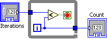
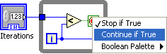
At times it is more convenient to let the while loop iterate while the condition is True. To change the loop condition , right click on the loop condition icon and select Continue if True from the pop-up menu.
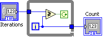
[link] shows the Loop Condition set to Continue if True .
Programmatically, while loop shift registers are identical to for loop shift registers . Refer to [link] for the discussion. However, an example is provided to illustrate the use of shift registers in while loops.
In the following example, Euler’s number e is computed to the specified accuracy using the infinite series
Notice that two shift registers keep track of the factorial and the sum. Also notice the dot in the multiplication. This is because the loop iteration is an integer 32 data type and the input from one of the shift registers is double precision numeric. The dot represents that the integer 32 data type has been coerced into a double precision number.
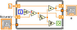
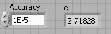
Save the program as e.vi . The result of running this program is shown in [link] .
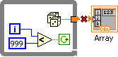
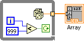
By default, while loops are auto-indexed disabled. In order for while loops to process and generate arrays, the loop tunnel must be enabled to auto-indexed arrays.
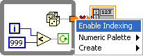
To enable auto-indexing, right click on the loop tunnel and select Enable Indexing from the pop-up menu.
In this example the while loop appropriately generates a 1,000 element numeric array with random numbers.
Although G was designed to easily develop interactive, parallel programs, it is sometimes necessary to execute diagrams in sequential order. The sequence structure allows G diagrams to execute sequentially.
The following examples time in milliseconds (ms) the execution of a G diagram. The sequence of events is get a start time stamp, execute the diagram, get stop time stamp and take the difference between the stop and start times to determine the execution time.
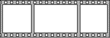
Flat Sequences always execute left to right. A Flat Sequence structure starts with a single frame and allows a user to visualize the diagram sequences.

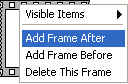
To add frames to a sequence, right click on the sequence structure and select either Add Frame After or Add Frame Before from the pop-up menu according to the program’s needs.
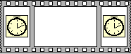
Add two more frames to the sequence structure to get a three frame sequence as shown in [link] .
From the Functions>>Programming>>Timing menu select Tick Count (ms) function.
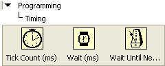
Drop the Tick Count (ms) function in the first (left most) frame of this sequence. Make a copy of the Tick Count function and place it on the third (right most) frame as shown in [link] .
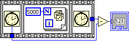
Add a For Loop that iterates 5,000 times to the second frame. Add a subtract operator, an unsigned integer 32 output and complete the program as shown in [link] . The execution of this program shows the time in milliseconds it took for the 2 nd sequential frame to execute.
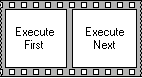
A Stacked Sequence provides a more compact representation of program sequences. It is programmatically identical to the Flat Sequence with the exception that a Sequence Local enables data to flow to subsequent frames. Additionally, as frames are added, a Sequence Selector provides access to the desired frame (see [link] ).
![A film frame with '0[0..1]' with arrows on either side pointing to the right and a down error.](/ocw/mirror/col11192_1.1_complete/m34089/Picture_327.png)
For this timing example, start with a Stacked Sequence and add 3 more frames. The sequence frames are labeled 0, 1, 2 and 3 and will execute in that order.
![A film frame with '3[0..3]' with arrows on either side pointing to the right and a down error.](/ocw/mirror/col11192_1.1_complete/m34089/Picture_328.png)
Go to the first frame (frame 0) and add a Tick Count (ms) function. Right click on the sequence structure and select Add Sequence Local from the pop-up menu.
![A film frame with '3[0..3]' with arrows on either side pointing to the right and a down error. A clock icon is contained in the middle of the frame.](/ocw/mirror/col11192_1.1_complete/m34089/Picture_329.png)
![A film frame with '3[0..3]' with arrows on either side pointing to the right and a down error. A menu is overlaid on top of this diagram with the item 'Add Sequence Local' is highlighted in blue.](/ocw/mirror/col11192_1.1_complete/m34089/Picture_332.png)
The Sequence Local is shown as an undefined tunnel. Wire the Tick Count (ms) function to the Sequence Local to define the tunnel data type and data flow. Data can now flow from frame 0 to the other frames as needed.
![A film frame with '3[0..3]' with arrows on either side pointing to the right and a down error. There is a clock icon in the middle of the frame with a hollow square on the lower left.](/ocw/mirror/col11192_1.1_complete/m34089/Picture_333.png)
![A film frame with '3[0..3]' with arrows on either side pointing to the right and a down error. There is a clock icon in the middle of the frame connected to a square containing a blue arrow on the lower left via a line.](/ocw/mirror/col11192_1.1_complete/m34089/Picture_334.png)
Go to the next frame sequence (frame 1) and enter the program to be timed.
![A film frame with '1[0..3]' with arrows pointing either direction and a down arrow at the top of the frame. Inside the frame there is an icon with a blue square on the left containing '5000' which is connected to a square containing a blue square 'N' in the upper left and a blue square 'i' in the lower left and dice on the middle. There is also a square arrow pointing to the right.](/ocw/mirror/col11192_1.1_complete/m34089/Picture_339.png)
Go to the third frame of the sequence (frame 2), add a Tick Count (ms) function, add another Sequence Local and wire the Tick Count (ms) to the new Sequence Local . The wired sequence frame is shown in [link] .
![A film frame with '2[0..3]' with arrows pointing either direction and a down arrow at the top of the frame. There is a clock icon in the middle of the frame with an arrow pointing left and another pointing right on the left wall of the frame.](/ocw/mirror/col11192_1.1_complete/m34089/Picture_340.png)
Go to the last frame (frame 3) and add a Subtract function. Wire the Sequence Locals from frame 2 and frame 0 to the Subtract function as shown in [link] . To complete the diagram, wire the output of the Subtract function to the unsigned integer 32 output.
![A film frame with '3[0..3]' with arrows pointing either direction and a down arrow at the top of the frame. Contained within the frame from left to right there are two blue square arrows pointing right with a blue line connecting to a triangle box containing '-' connected to a blue square on the left edge of the frame wall. A line connects this box to a blue box on the outside of the frame.](/ocw/mirror/col11192_1.1_complete/m34089/Picture_341.png)
It is important to note that the programs in [link] and [link] are programmatically identical.
Notification Switch
Would you like to follow the 'Introduction to g programming' conversation and receive update notifications?

|
|

|
|

|
|

|
|

|
|

|
|

|
|

|
|

|
|

|