

| << Chapter < Page | Chapter >> Page > |
The spectral peaks in Figure 7 appear where you would expect to see them. For example, the location of the peak in the first plot corresponds to a frequencyof 0.25 cycles per second within a total frequency range extending from zero to two cycles per second. This matches the information given in the above table forthe first sinusoid.
The location of the spectral peak in the fifth plot corresponds to a frequency of 1.75 cycles per second within a total frequency range extendingfrom zero to two cycles per second. This matches the information given in the above table for the fifth sinusoid.
The location of the peak in each of the three plots between the first and the last are correct for the frequency of the sinusoid involved.
Now I will introduce a sampling problem by keeping the frequencies of the sinusoids the same and reducing the sampling frequency from four samples persecond to two samples per second.
The result of this change is shown in Figure 8 .
| Figure 8. Spectral analyses of five sinusoids with sampling problem. |
|---|
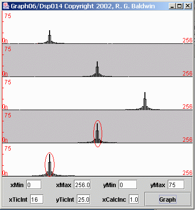 |
As before, each of the plots in Figure 8 shows the frequency spectrum of an individual sinusoid. The spectrum is plotted from zero frequency on the left tothe folding frequency on the right.
In this case, the sampling frequency was two samples per second, giving a folding frequency of one cycle per second. Therefore, the horizontal scale oneach plot represents the frequencies from zero on the left to one cycle per second on the right.
Once again, the height of each spectral peak is consistent with the amplitude of the sinusoid.
As before, the spectral peaks in the first three plots appear where you would expect to see them. The peak in the first plot is about twenty-five percent ofthe way across the total spectrum, corresponding to 0.25 cycles per second.
The spectral peak in the second plot is at the center, corresponding to 0.5 cycles per second. The third peak is in the correct location for 0.75 cycles persecond.
However, a problem exists with the spectral peaks in the last two plots.
(I marked the two problem peaks with a red oval to make it obvious which ones I am talking about. You may find it helpful to compare Figure 8 side-by-side with Figure 7 .)
The spectral peak in the fourth plot also appears about midway between zero and one cycle per second. This indicates that the corresponding sinusoid had afrequency of 0.5 cycles per second.
However, the frequency of the sinusoid for the fourth plot was 1.50 cycles per second, not 0.5 cycles per second as indicated. Thus, that spectral peakshould have been off the scale on the right-hand side of the plot.
Recall, however, that the right edge of the plot is the folding frequency. Therefore, any spectral components that should appear to the right of thefolding frequency fold around and appear to the left of the folding frequency. Therefore, the spectral peak in the fourth plot, which should appear at 0.50cycles per second above the folding frequency, appears instead at 0.50 cycles per second below the folding frequency.
Notification Switch
Would you like to follow the 'Digital signal processing - dsp' conversation and receive update notifications?

|
|

|
|

|
|

|
|

|
|

|
|

|
|
|
|
|

|
|

|