We used the average of these readings, i.e., (0.13+0.23)/2 = 0.18 and rounded to 0.2 sec.
Real-time system design
The system design comprises two parts:
Simulation, to determine the parameters of the Speed Control Transfer Function
Hardware Design of the interface circuit.
Simulation
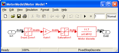
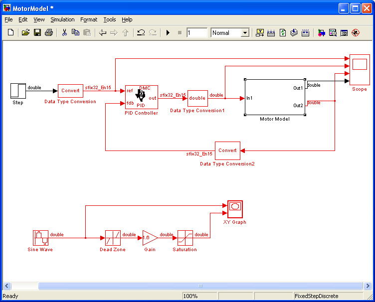
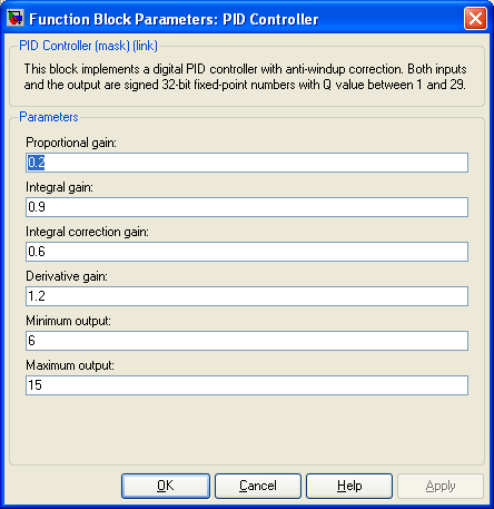
The speed control is a PID controller. A DC motor model (Figure 14) was created. The complete control loop model is shown in Figure 15. Figure 16 shows the parameters chosen for the PID controller.
DC Motor ModelLoop Control ModelPID Controller Parameters
Hardware design
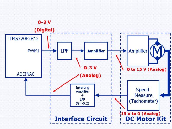
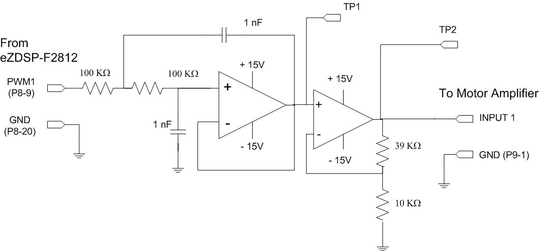
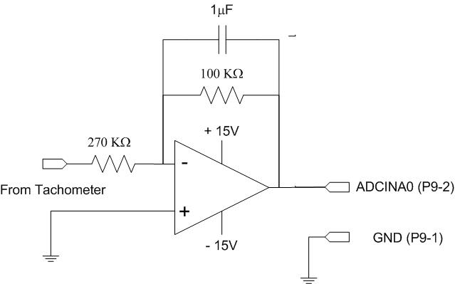
The connection between the eZDSP and the Motor Kit requires a dedicated interface circuit, implementing the Low Pass Filter (used for the Digital to Analog conversion) and adapting the voltage levels at the eZDSP (0 to 3V) to those of the DC Motor Kit (0-15V). The various signal types and their voltage range are shown in .
The interface circuit contains two blocks. The first is LPF with an amplifier (shown in Figure 18), connected between the PWM output and the servo amplifier input. The second block is an attenuator (shown in Figure 19) connected between the tachometer output and the Analog to Digital Input of the eZDSP.
Signal Types and Voltage Levels
LPF + Amplifier CircuitThe Inverting Amplifier with LPF
Real time implementation
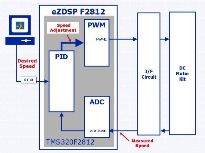
The control loop was implemented in the eZDSP F2812 as shown in Figure 20. The PID controller obtained in the previous chapter was implemented in the DSP. The environment is shown in Figure 21.
The real-time implementation model will be created from the "DC Motor Speed Control via RTDX" SIMULINK demo. In the original demo model the loop is closed by QEP block, we will use a tachometer connected to the Analog to Digital Converter module for speed measurement.
The Model and its subsystems are shown in Figures Figure 22, Figure 23 and Figure 24.
Copy the following files into your working directory:
c2812speedcontrolDC.mdl
runc2812speedcontrolDC.m
runc2812speedcontrolDC.m
Open the c2812speedcontrolDC.mdl model and save it as "DCMotorControlc2812.mdl"(please refer to Figure 21
The model is shown here after deleting the “Info” box. ).
Real-Time Implementation Model
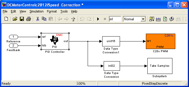
Double-click the Speed Correction Block, and you will see:
Figure 22: Speed Control
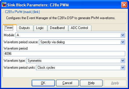
Configure the C28x PWM block as follows:
Figure 23: PWM Configuration
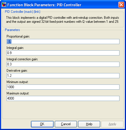
Configure the "PID Controller" block as follows:
PID Configuration
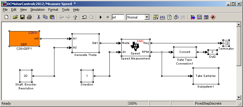
Double-click the Speed Correction Block, and you will see:
QEP Based Speed Measurement
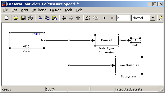
Delete the selected blocks and replace them by the ADC block from Open the ADC block from the C281x Chip support group from the C2000 Target Preferences, and connect is as follows:
ADC+Tachometer Based Speed Measurement
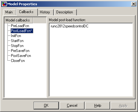
Now the model is ready for real-time, we need however to update the MATLAB script file. Open the “Model Properties” from “File” menu. Change the PostLoadFcn callback to runc2812speedcontrolIDC, as shown:
Model Callback
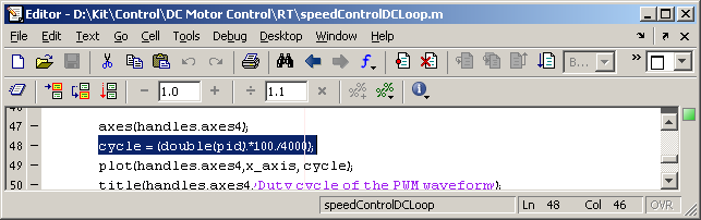
The next step is to change the original PWM range (up to 64000) to the desired range (up to 4000). Open the “speddControlIDCLoop.m” file with the MATLAB editor, an change on line 48 the command:
cycle = (double(pid).*100./64000);to
cycle = (double(pid).*100./4000);
Please refer to the following picture:
Changing the PWM range
Activate the motor
Activate CCS.
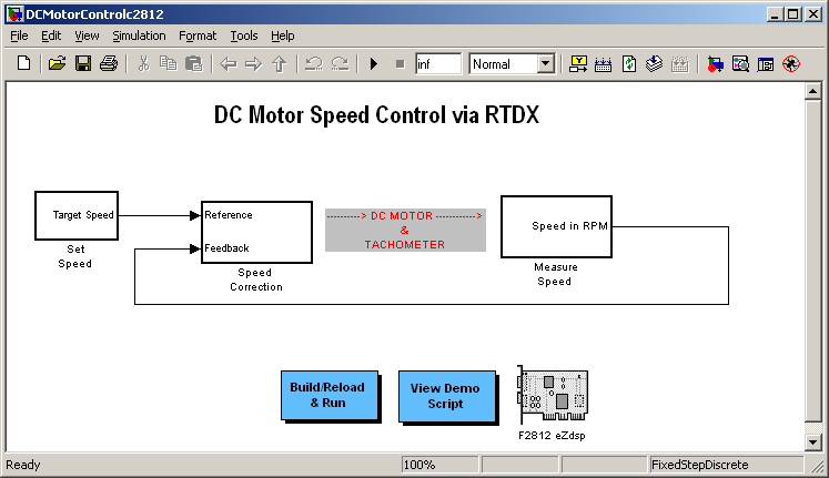
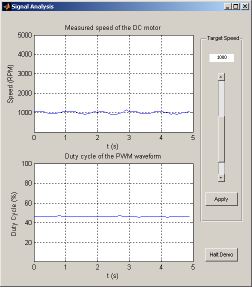
Click the Build/Reload&Run box, the following window should appear:
Speed Control GUI
You may change the speed of the motor using the slider in the right hand side and the “Apply” button.
Receive real-time job alerts and never miss the right job again
Source:
OpenStax, From matlab and simulink to real-time with ti dsp's. OpenStax CNX. Jun 08, 2009 Download for free at http://cnx.org/content/col10713/1.1
Google Play and the Google Play logo are trademarks of Google Inc.
Notification Switch
Would you like to follow the 'From matlab and simulink to real-time with ti dsp's' conversation and receive update notifications?