Low-side injection results in symmetry in the translated message
spectrum about
on each of the positive and negative half-axes.
High-side injection separates the undesired images
further from the lower frequency portion (which will ultimatelybe retained to reconstruct the message). This
eases the requirements on the bandpass filter.
Both high-side and low-side injection can place
frequency interferers in undesirable places.This highlights the need for adequate out-of-band rejection
by a bandpass filter before downconversion to IF.
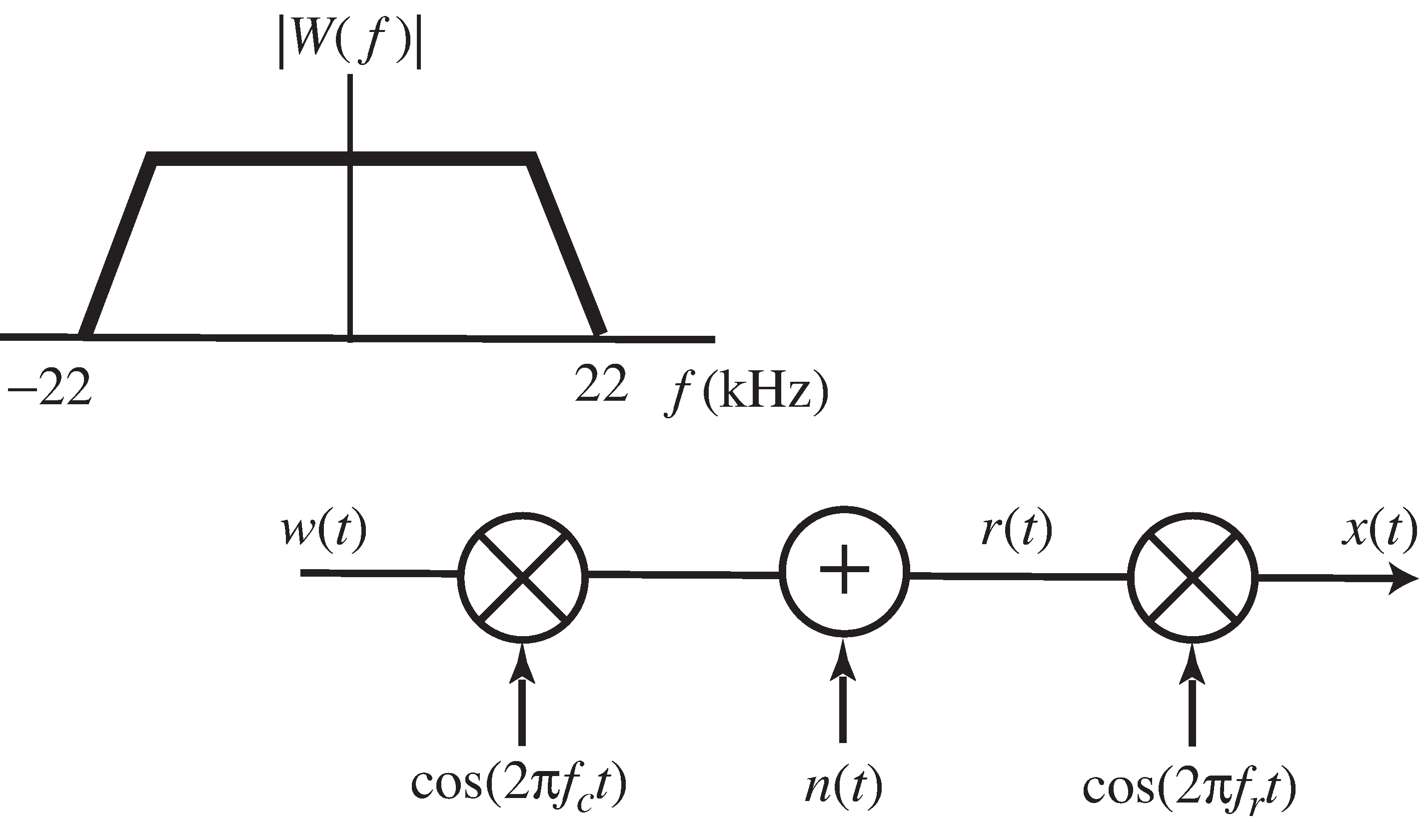
Consider the system described in
[link] .
The message
has a bandwidth of 22kHz
and a magnitude spectrum as shown.The message is upconverted by a mixer with carrier frequency
.
The channel adds an interferer
.
The received signal
is downconverted to the IF signal
by a mixer with frequency
.
With
,
kHz, and
kHz,
indicate all frequency ranges (i)-(x) that include any partof the IF passband signal
.
(i) 0-20 kHz,(ii) 20-40 kHz,
(iii) 40-60 kHz,(iv) 60-80 kHz,
(v) 80-100 kHz,(vi) 100-120 kHz,
(vii) 120-140 kHz,(viii) 140-160 kHz,
(ix) 160-180 kHz,(x) 180-200 kHz
With
kHz and
kHz,
indicate all frequency ranges (i)-(x) that include anyfrequency that causes a narrowband interferer
to appear
in the nonzero portions of the magnitude spectrum ofthe IF passband signal
.
With
kHz and
kHZ,
indicate every range (i)-(x) that includes anyfrequency that causes a narrowband interferer
to appear
in the nonzero portions of the magnitude spectrum ofthe IF passband signal
.
A transmitter operates as a standard AM with suppressed carrier transmitter
(as in
AM.m ). Create a
demodulation routine that operates in two steps:by mixing with a cosine of frequency
and subsequently mixing with a cosine of
frequency
. Where must pass/reject
filters be placed in orderto ensure reconstruction of the message?
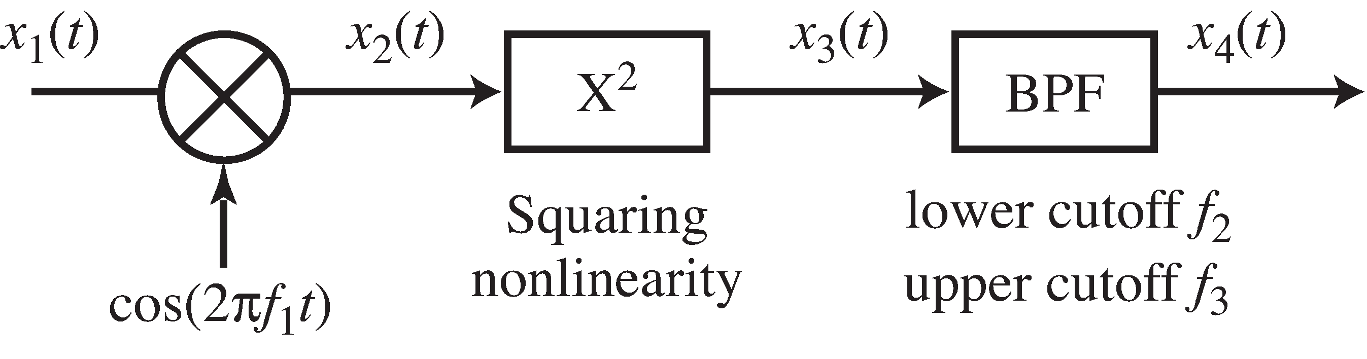
Let
.
Consider the schematic shown in
[link] with the absolute bandwidth of the baseband signal
of 4 kHz,
kHz,
kHz, and
kHz.
Using your M
atlab code from Exercise
[link] , investigate
the effect of a sinusoidal interference:
at frequency
,
at frequency
,
at frequency
.
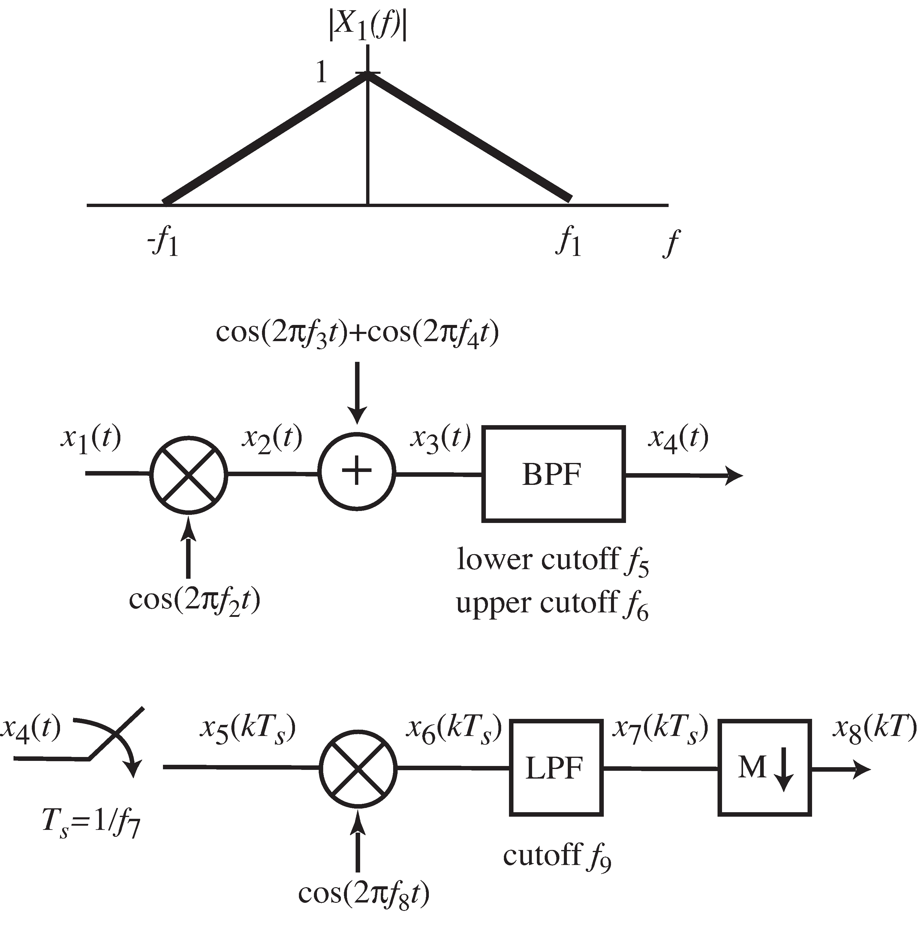
Consider the PAM communication system
in
[link] .
The input
has a triangular baseband magnitude spectrum.
The frequency specifications are
kHz,
kHz,
kHz,
kHz,
kHz,
kHz,
and
kHz.
Draw the magnitude spectrum
between
kHz.
Be certain to give specific values of frequency andmagnitude at all breakpoints and local maxima.
Specify values of
and
for which the system
can recover the original message without corruption with
.
This problem asks you to build a receiver from a limited
number of components.The parts available are:
two product modulators
with input
and output
related
by
and carrier frequencies
of 12 MHz and 50 MHz
two linear bandpass filters with ideal rectangular magnitude spectrum
of gain one between
and
and between
and
and zero elsewhere with (
,
) of
(12MHz, 32MHz) and (35MHz, 50MHz).
two impulse samplers with input
and output
related by
with sample periods of 1/15 and 1/12 microseconds
one square law device
with input
and output
related by
three summers with inputs
and
and output
related by
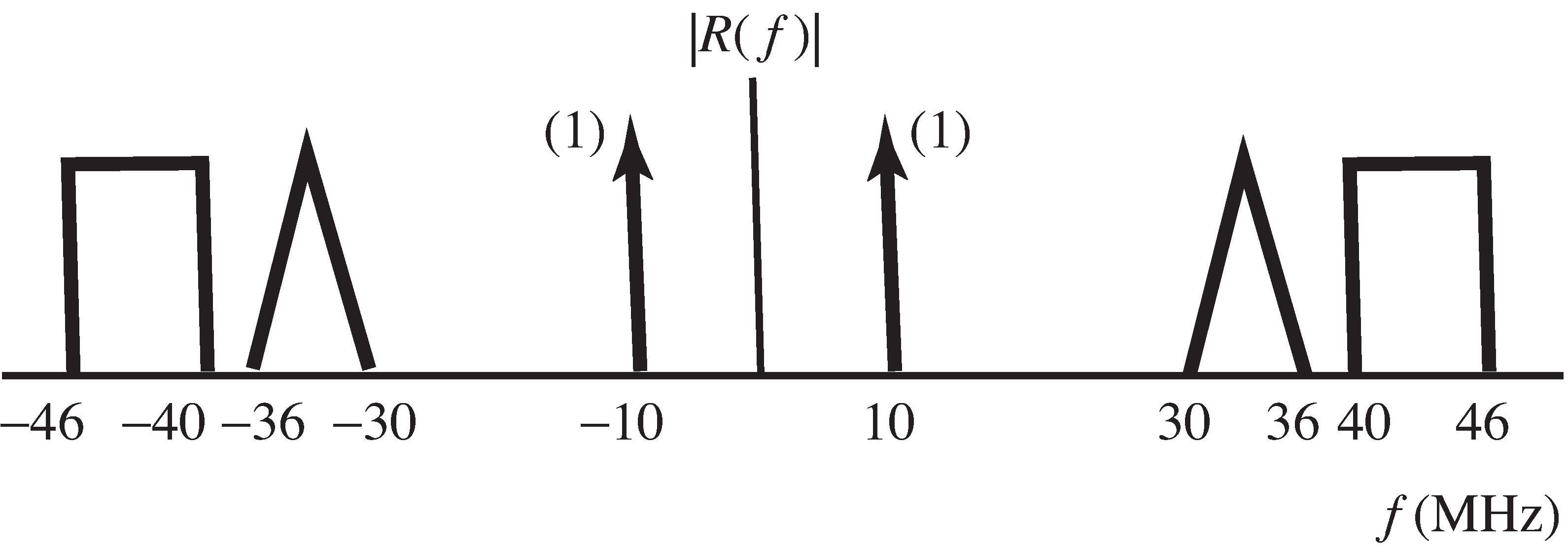
The spectrum of the received signal is illustrated
in
[link] .
The desired baseband output of the receivershould be a scaled version of the triangular portion
centered at zero frequency with no other signalsin the range between
and 8 MHz.
Using no more than four parts from the 10 available,build a receiver that produces the desired baseband signal.
Draw its block diagram.Sketch the magnitude spectrum of the output of each part
in the receiver.
Spectrum of the received signal for Exercise
[link]
For further reading
A friendly and readable introduction to analog transmission systems can be found in
P. J. Nahin,
On the Science of Radio , AIP Press, 1996.