What is the impedance
at the frequency of
the source?
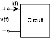
Black-box circuit
You are given a
circuit that has two terminals for
attaching circuit elements.
When you attach a voltage source equaling
to the terminals, the current through the source equals
.
When no source is attached (open-circuited terminals),the voltage across the terminals has the form
.
What will the terminal current be when you replace thesource by a short circuit?
If you were to build a circuit that was identical
(from the viewpoint of the terminals) to the givenone, what would your circuit be?
For your circuit, what are
and
?
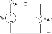
Solving a mystery circuit
Sammy must determine as much as he can about a mystery
circuit by attaching elements to the terminal andmeasuring the resulting voltage. When he attaches a 1Ω
resistor to the circuit's terminals, he measuresthe voltage across the terminals to be
.
When he attaches a 1F capacitor across the terminals,the voltage is now
.
What voltage should he measure when he attaches
nothing to the mystery circuit?
What voltage should Sammy measure if he doubled the
size of the capacitor to 2 F and attached it to thecircuit?
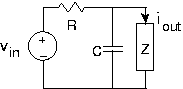
Find the load impedance
The
depicted circuit has a transfer function between the
output voltage and the source equal to
.
Sketch the magnitude and phase of the transfer
function.
At what frequency does the phase equal
?
Find a circuit that corresponds to this loadimpedance. Is your answer unique? If so, show it to be
so; if not, give another example.
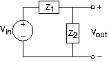
Analog “hum” rejection
“Hum” refers to corruption from wall socket
power that frequently sneaks intocircuits. “Hum” gets its name because it
sounds like a persistent humming sound. We want to finda circuit that will remove hum from any signal. A Rice
engineer suggests using a
simple voltage divider circuit consisting of two series impedances.
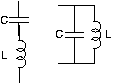
The impedance
is a resistor. The Rice engineer must decide between
two circuits for the impedance
.
Which of these will work?
Picking one circuit that works, choose circuit elementvalues that will remove hum.
Sketch the magnitude of the resulting frequency
response.
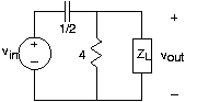
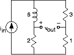
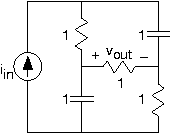
An interesting circuit
For the circuit shown in
[link] ,
find the transfer function.
What is the output voltage when the input has the form
?
What is the transfer function between the source and
the output voltage?
What will the voltage be when the source equals
?
Many function generators produce a constant offset in
addition to a sinusoid. If the source equals
,
what is theoutput voltage?
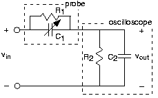
An interesting and useful circuit
The
depicted circuit has interesting properties, which
are exploited in high-performance oscilloscopes.
The portion of the circuit labeled "Oscilloscope"
represents the scope's input impedance.
and
(note the label under the channel 1 input in the lab'soscilloscopes). A
probe is a device
to attach an oscilloscope to a circuit, and it has theindicated circuit inside it.
Suppose for a moment that the probe is merely a wire
and that the oscilloscope is attached to a circuitthat has a resistive Thévenin equivalent
impedance. What would be the effect of theoscilloscope's input impedance on measured voltages?
Using the node method, find the transfer function
relating the indicated voltage to the source whenthe probe is used.
Plot the magnitude and phase of this transfer
function when
and
.
For a particular relationship among the elementvalues, the transfer function is quite simple. Find
that relationship and describe what is so specialabout it.
The arrow through
indicates that its value can be varied. Select the
value for this capacitor to make the specialrelationship valid. What is the impedance seen by
the circuit being measured for this special value?