

| << Chapter < Page | Chapter >> Page > |
While other types of filters are often of interest, this note focuses on the lowpass linear phase filter. Even though it is not immediately obvious, virtuallyall of the analytical results developed in this note apply to the other types as well. This fact is amplified in the module Extension to Non-lowpass Filters .
It is known that the Parks-McClellan filter synthesis software package produces “optimal" filters in the sense that the best possible filter performance isattained for the number of “filter taps" allowed by the designer. “Optimal" can be defined various ways. The Parks-McClellan package uses the Remezexchange algorithm to optimize the filter design by selecting the impulse response of given length, termed here , which minimizes the peak ripple in the passband and stopband. It can be shown, though not here, that minimizingthe peak, or maximum, ripple is equivalent to making all of the local peaks in the ripple equal to each other. This fact leads to three different names foressentially the same filter design. They are commonly called “equal-ripple" filters, because the local peaks are equal in deviation from the desired filterresponse. Because the maximum ripple deviation is minimized in this optimization procedure, they are also termed “minimax" filters. Finally, since the RussianChebyshev is usually associated with minimax designs He developed the concept of minimax design and a set of polynomials which carry his name not fromfilter design, but from the optimal design of piston drive rods for steam locomotives. They are discussed more in "Filter Sizing" and Appendix B . , these filters are often given his name.
The design template for an equal-ripple lowpass filter is shown in [link] .
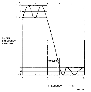
The passband extends from 0 Hz to the cutoff frequency denoted . The gain in the passband is assumed to be unity. Any other gain isattained by scaling the whole impulse response appropriately. The stopband begins at the frequency denoted and ends at the so-called Nyquist or “folding" frequency, denoted by , where is the sampling frequency of the data entering the digital filter. In somereferences, [1] for example, the sampling rate is assumed to be normalized to unity just as the passband gain has here. The dependence onthe sampling frequency is kept explicit in this note, however, so that its impact on design parameters can be kept visible.
The optimal synthesis algorithm is assumed here to produce an impulse response whose associated frequency response has ripples in both the passbandand the stopband. The peak deviation in the passband is denoted and the peak deviation in the stopband is denoted . It is commonly thought that an “equal-ripple" design forces to equal . In fact this is not true. The local ripple peaks in the passband will allequal and those in the stopband will all equal . For a given filter specification the two are linked together by a weight denoted , so that . In fact the Parks-McClellan routines insure the design of weighted equal-ripple filters. The choice of is discussed shortly.
An important design parameter is the transition band , denoted , and defined as the difference between the stopband edge and the passband edge . Thus,
In theory the required filter order is a function of all of the design parameters defined so far, that is, , and . The central point of this technical note is that under a large range of practical circumstances the required value of can be estimated using only , and the smaller of and .
While the parameters defined in the previous section relate directly to the theory of FIR filter design optimization, some of them differfrom those usually employed to specify the performance of a filter. We discuss here the conversion of two of those, and , into more traditional measures.
Passband Ripple : [link] uses the parameter to describe the peak difference between the template lowpass filter and the magnitude of the filter response actually attained.Traditionally this passband ripple has been specified in terms of the maximum difference in the power level transmitted through the filter inthe passband. By this definition, the peak-to-peak passband ripple, abbreviated here asPBR, is given by
Assuming that the nominal power transmission through the filter is unity, the numerator is the power gain at a ripple peak and the denominator isthe gain at a trough. It is easily shown (see Appendix A ) that when is small compared to unity, or, equivalently, when the passband ripple is less than about 1.5 dB, then Strictly speaking, the peak ripple excursions are equal in magnitude, not in decibels. Thissubtlety is completely negligible for small values of .
Stopband Ripple : The traditional specification forstopband ripple, abbreviated here as SBR, is the power difference between the nominal passband transmission level and the transmission level of thehighest ripple in the stopband. For the equal ripple design shown in [link] , all stopband ripples have equal peak values and the nominal passband transmission is unity, that is, 0 dB. The stopbandripple, or more accurately, the minimum stopband power rejection, denoted SBR, is given by
Suppose a filter is specified to have a peak-to-peak passband ripple of 0.5 dB and a minimum stopband attenuation of 60 dB.Using the above equations we find that , , and the relative weighting, , therefore equals 28.8.
In discussing filter specifications it should be noted that the cutoff frequency shown in [link] differs from the definition typically used in analog filter designs. The cutofffrequency is commonly defined as the 3 dB point , that is, that frequency at which the power transfer function fallsto a value 3 dB below the nominal passband level. Instead the value of shown in [link] is the highest frequency at which the specified passband ripple is still attained. In very few practical cases do thetwo definitions result in the same value.
Notification Switch
Would you like to follow the 'Notes on the design of optimal fir filters' conversation and receive update notifications?

|
|

|
|

|
|

|
|

|
|

|
|

|
|

|
|
|
|
|
|
|